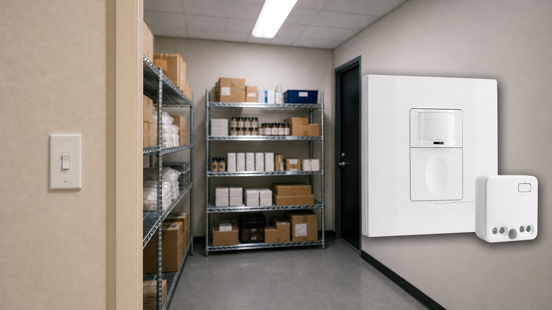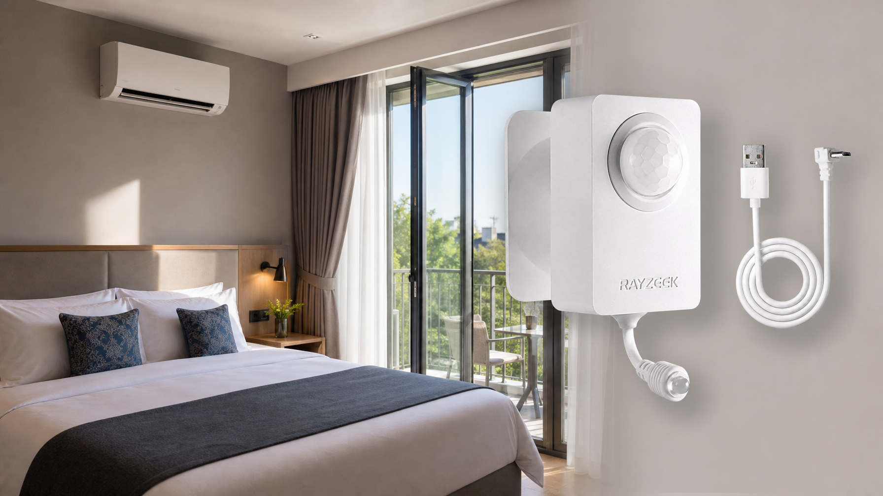
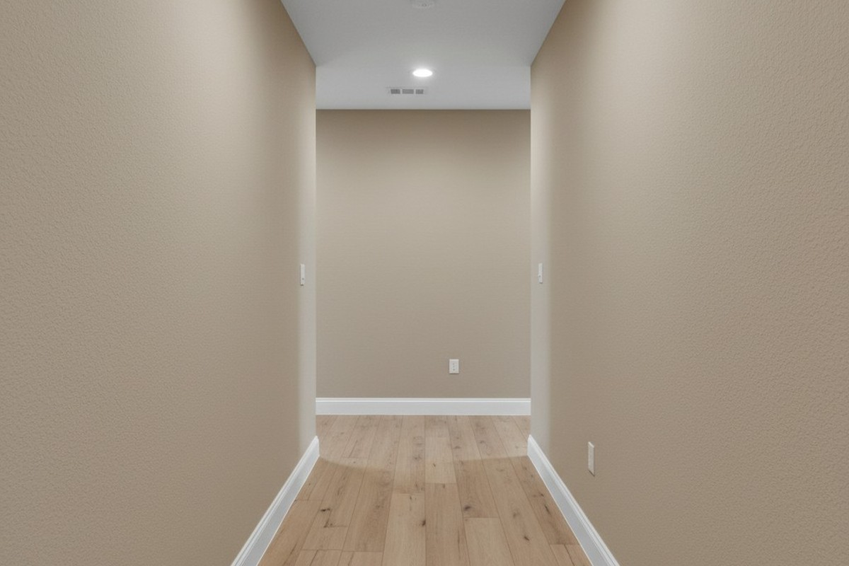
You’ve likely seen this in a commercial building, or maybe even your own hallway. You walk out of a bedroom, hands full of laundry or groceries, into the dark. You take three steps toward the kitchen, expecting the motion sensor to catch you, but the hallway stays pitch black. You have to walk another ten feet, almost to the end of the hall, before the lights finally snap on. Or worse, you find yourself doing the “waving arms” dance in the dark, hoping to catch the sensor’s attention.
This is a geometry failure, not just a nuisance. It happens because someone treated an L-shaped hallway like a straight line. They swapped out an existing switch for a motion sensor, assumed the “180-degree field of view” on the box was magic, and called it a day. But physics doesn’t care about your convenience, and infrared heat signatures can’t bend around drywall. If the sensor can’t see you, the lights stay off. It’s that simple.
Why the L-Shape Defeats Standard PIR
To fix this, you have to understand what the sensor is actually doing. Most residential sensors, including the Rayzeek RZ series, use Passive Infrared (PIR) technology. They look for a heat differential moving across a Fresnel lens.
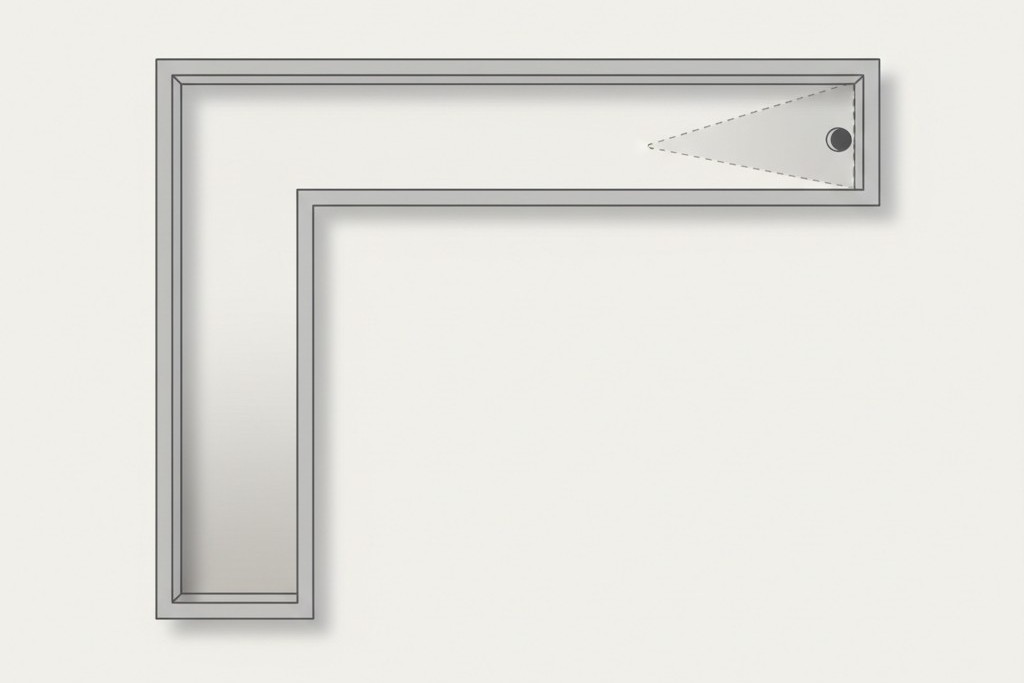
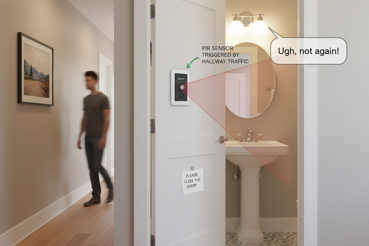
Think of the sensor like a flashlight beam. If you taped a flashlight to the switch box, where would the light hit? In an L-shaped hallway, usually with switch boxes at the far ends of the “legs,” that beam hits the opposite wall and stops. The other leg of the hallway stays in shadow.
There’s a misconception that these sensors work like radar or sonar, bouncing signals around corners. They don’t. (Ultrasonic sensors exist, mostly in commercial bathrooms, but they’re overkill for a house and prone to false triggers every time the HVAC kicks on). For a standard PIR switch, line-of-sight is non-negotiable. If you’re standing in the “shadow” of the corner—the area the lens physically can’t see—you don’t exist to the system.
This is also why “pet immunity” is such a headache in these layouts. People try to mask the bottom of the lens to avoid the cat triggering the lights at 3 AM, which further narrows the vertical detection cone. If you have bad horizontal placement そして you tape off the bottom of the lens, you’ve effectively built a light switch that requires you to stand directly in front of it and wave.
So, how do you solve the blind corner? You have two options: a carpenter’s solution (moving the device) or an electrician’s solution (wiring a network).
Strategy 1: The Fulcrum Mount (The Carpenter’s Fix)
In many retrofits—specifically in older farmhouses or renovations where the layout is quirky—the existing switch boxes are in the worst possible spots, usually at the far ends of the hallway. If you install a sensor at the end of the hall, it only sees down one leg. The most robust fix is often to ignore the electrical boxes you have and cut in a new one where you actually need it.
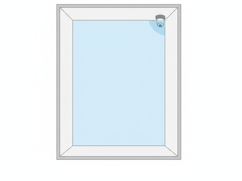
We call this the Fulcrum Strategy. You identify the outer corner of the “L”—the vertex where the two hallways meet. If you place a wide-angle sensor (like the Rayzeek RZ021) on that corner, usually ceiling-mounted or high on the wall, it has a clear shot down both legs of the hallway. It’s the sniper’s perch of motion detection.
こちらの商品もおすすめです

- 電圧: 単4形乾電池 2本
- 昼/夜モード
- タイマー設定時間: 15分、30分、1時間(デフォルト)、2時間
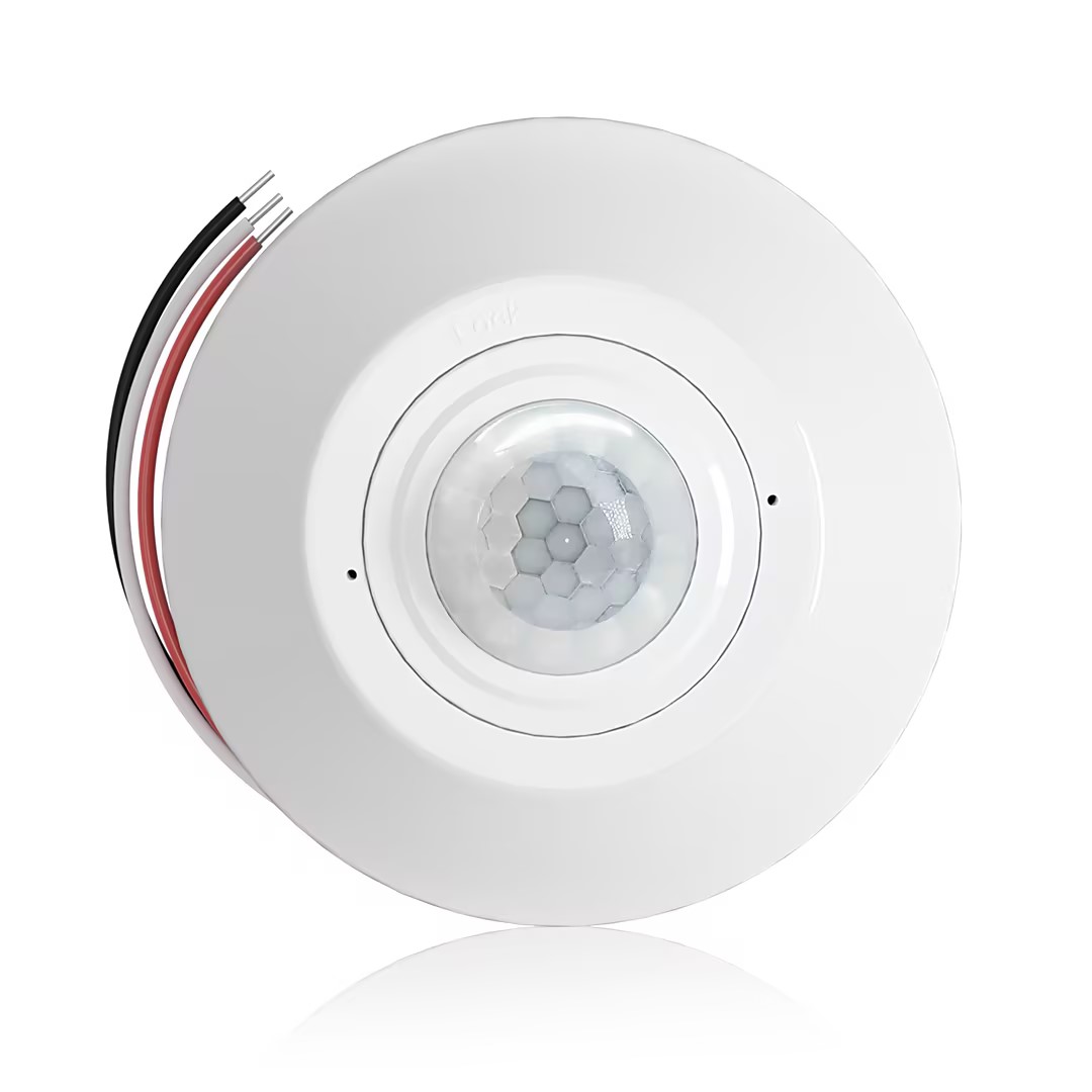
- 無電圧接点リレー出力付き天井取り付け型PIR人感センサー
- 12/24VDCまたは12/24VAC低電圧電源
- EMS、HVAC、および建物制御入力用COM、NO、NC絶縁リレー接点
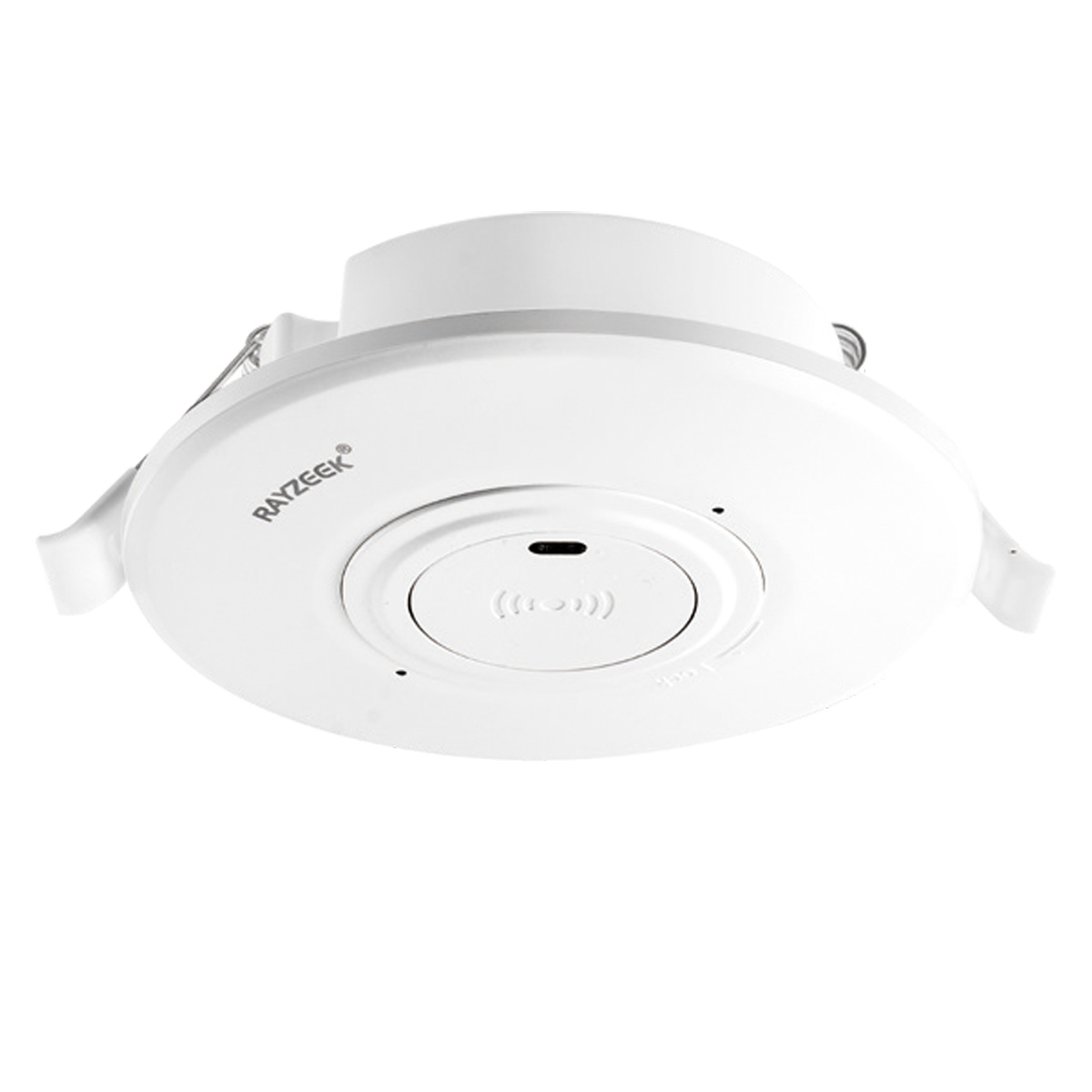
- 低電圧DC天井埋め込み型マイクロ波人感センサースイッチ
- 10~30 VDC範囲の12 VDC / 24 VDC入力
- 調整可能なタイムラグ、照度(Lux)閾値、感度を備えた最大動作電流10A仕様
- 高負荷対応型 埋込型天井取付けマイクロ波人感センサースイッチ
- 100-265 VAC 商用電源入力、10Aモデル
- 調整可能なタイムラグ、照度(Lux)閾値、感度を備えた5.8 GHzマイクロ波検知
- 埋込型天井取付けマイクロ波人感センサースイッチ
- 100-265 VAC商用電圧入力、5Aモデル
- 調整可能なタイムラグ、照度(Lux)閾値、感度を備えた5.8 GHzマイクロ波検知
- 220V電源対応 天井取付けRZ037 PIR(赤外線)人感センサー調光器
- 定格負荷660W、最大動作電流3A
- LUXボタンによる照度センサーのON/OFFおよびユーザー設定の調光明るさ制御
- 110V電源対応 天井取付けRZ037 PIR(赤外線)人感センサー調光器
- 定格負荷330W、最大動作電流3A
- LUXボタンによる照度センサーのON/OFFおよびユーザー設定の調光明るさ制御
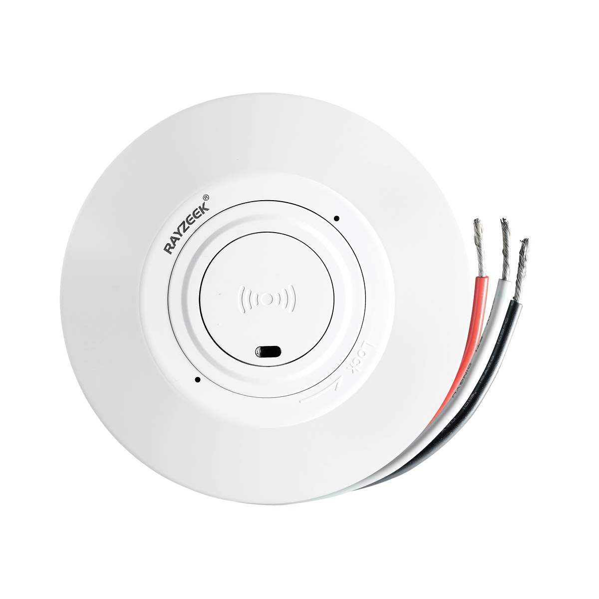
- 低電圧DC対応 天井取付けマイクロ波人感センサースイッチ
- 10~30 VDC範囲の12 VDC / 24 VDC入力
- 調整可能なタイムラグ、照度(Lux)閾値、感度を備えた最大動作電流10A仕様
- 高負荷対応 天井取付型マイクロ波人感センサースイッチ
- 100-265 VAC 商用電源入力、10Aモデル
- 調整可能なタイムラグ、照度(Lux)閾値、感度を備えた5.8 GHzマイクロ波検知
- 天井取り付け型マイクロ波人感センサースイッチ
- 100-265 VAC商用電圧入力、5Aモデル
- 調整可能なタイムラグ、照度(Lux)閾値、感度を備えた5.8 GHzマイクロ波検知
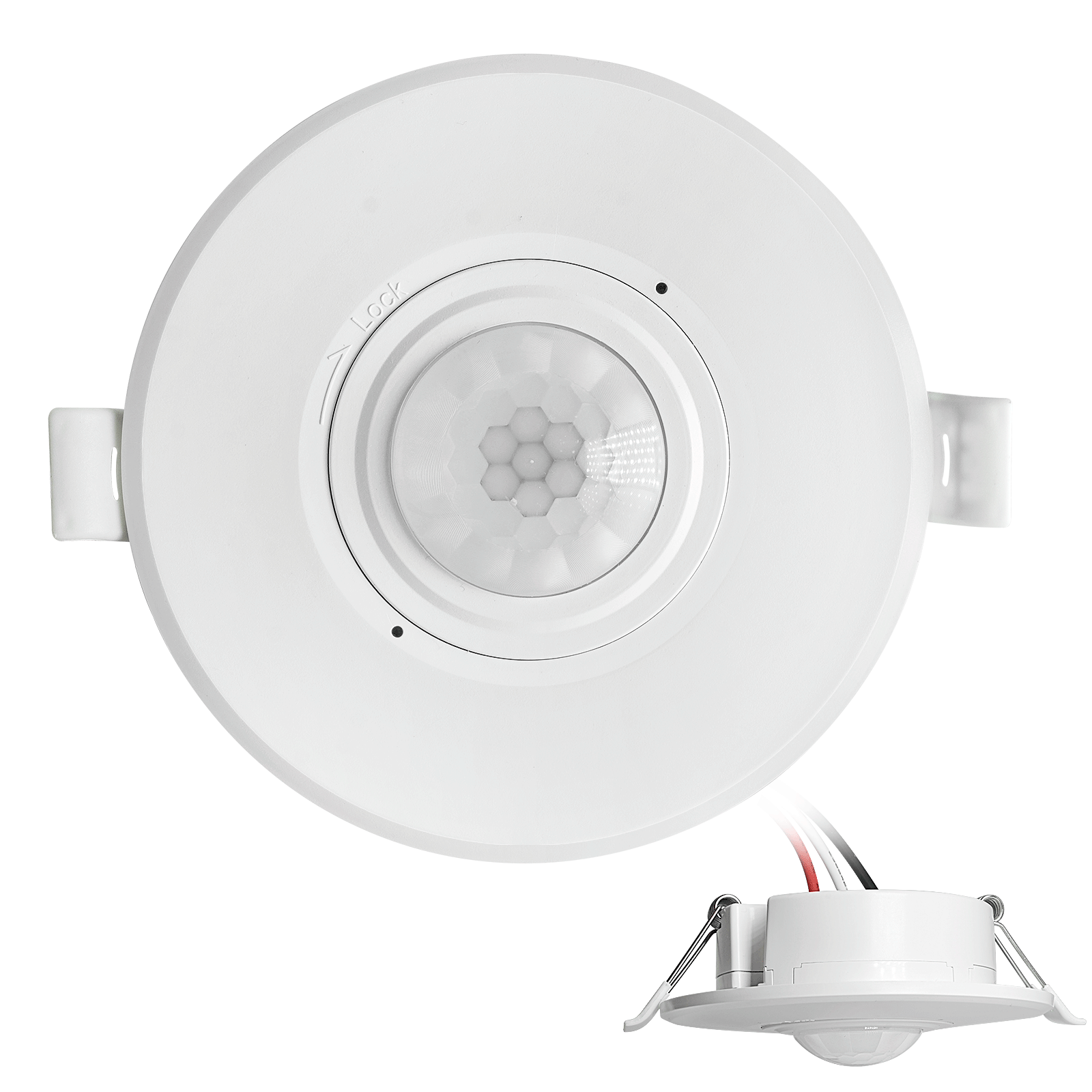
- 低電圧DC埋込型天井PIR人感センサースイッチ
- 10~30 VDC範囲の12 VDC / 24 VDC入力
- 最大動作電流10A(調整可能なタイムラグ、照度閾値、感度設定付き)
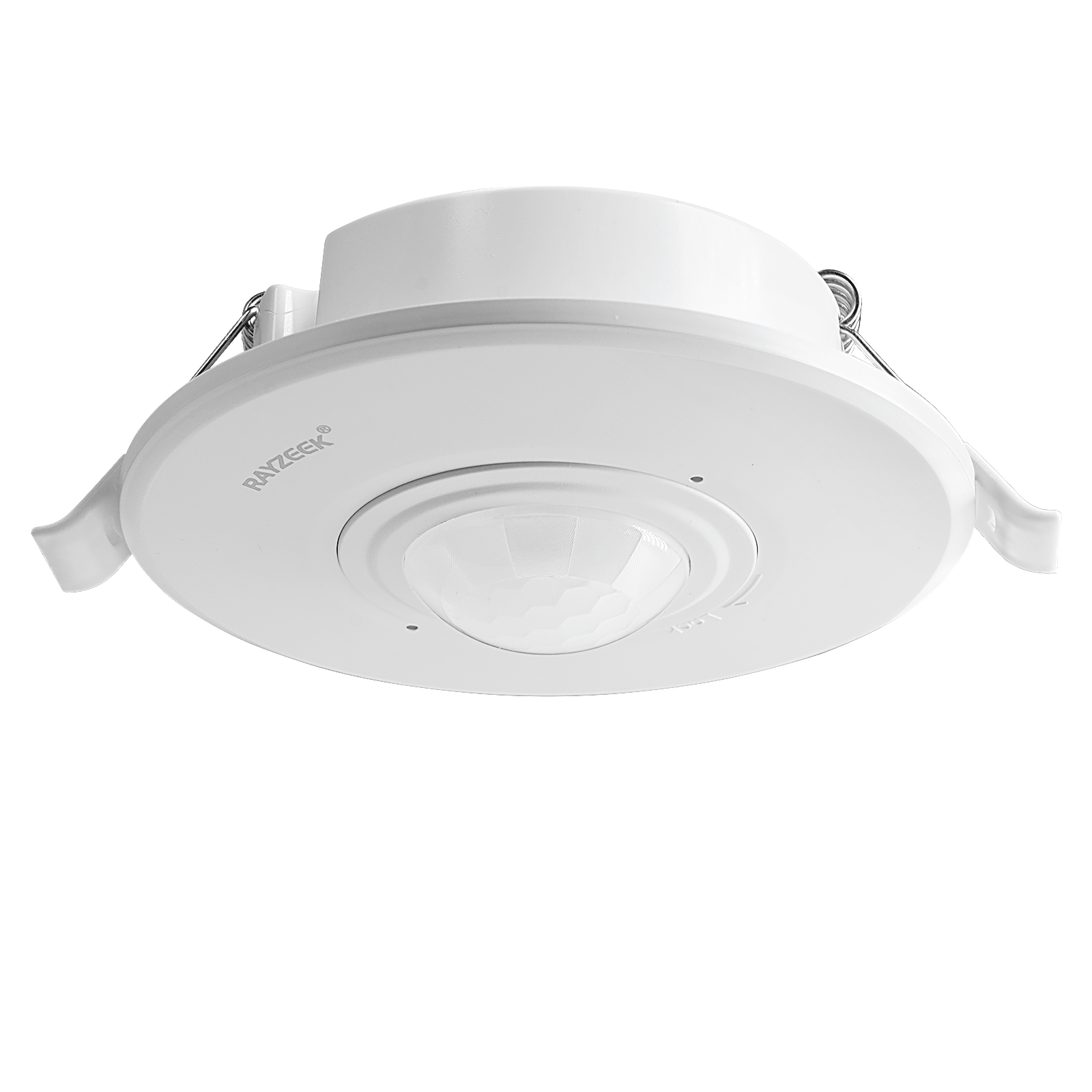
- 高負荷対応 埋込型天井PIR人感センサースイッチ
- 100-265 VAC 商用電源入力、10Aモデル
- 360度検知(調整可能なタイムラグ、照度閾値、感度設定付き)
- 埋込型天井PIR人感センサースイッチ
- 100-265 VAC商用電圧入力、5Aモデル
- 360度検知(調整可能なタイムラグ、照度閾値、感度設定付き)
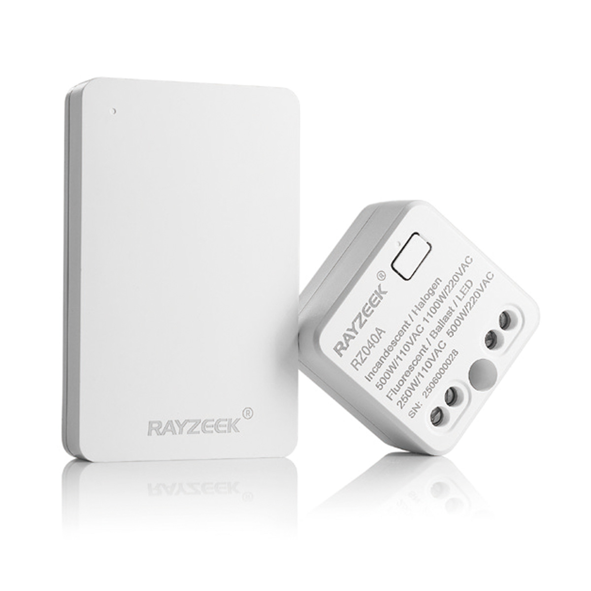
- 屋内用照明ON/OFF制御ワイヤレススイッチ&受信機キット
- 100-230VAC、50/60Hz、定格電流5A受信機
- 2.4GHz通信対応 CR2032電池駆動ワイヤレススイッチ
- Occupancy(自動点灯/自動消灯)
- 12–24V DC (10–30VDC)、最大10A
- 360°検知エリア、直径8–12m
- タイムラグ 15秒–30分
- 照度センサー オフ/15/25/35 Lux
- 高/低感度
- 自動点灯/自動消灯人感モード
- 100–265V AC, 10A(中性線必須)
- 360°検知範囲、検知直径8–12 m
- タイムデレイ15秒–30分、Lux OFF/15/25/35、感度 高/低
- 自動点灯/自動消灯人感モード
- 100–265V AC, 5A(中性線必須)
- 360°検知範囲、検知直径8–12 m
- タイムデレイ15秒–30分、Lux OFF/15/25/35、感度 高/低
This requires getting your hands dirty. You’ll need a “cut-in” or “old work” box (like the blue Carlon boxes with the flip-out wings), a drywall saw, and a fish tape. You pull the line voltage from one of the existing switch locations, snake it through the ceiling or attic, and drop it down to this new corner location. You then blank off the old switches or turn them into permanent power feeds.
It sounds like more work, but run the math on the callback cost. Spending an hour fishing a wire and patching a small square of drywall is cheaper than buying wireless battery-powered sensors that fail every six months, or coming back three times because the client is complaining about the lights not turning on. With the sensor at the fulcrum, the geometry problem is solved instantly. One device, 100% coverage, zero blind spots.
Strategy 2: The Wired 3-Way (The Electrician’s Fix)
If you can’t cut into the drywall—maybe it’s a condo with concrete walls or a high-end finish you can’t touch—you have to use the existing box locations. This means you need two sensors, one at each end of the L, working together. This is where most installations go wrong because people assume a motion sensor wires up exactly like a mechanical 3-way switch. It doesn’t.
In a standard mechanical 3-way, the switches toggle power back and forth along “traveler” wires. If you just swap those mechanical switches for sensors, you often end up with a system where one sensor kills power to the other, or they fight for control. The lights might strobe, or one end of the hall will work while the other is dead.
For Rayzeek units (and similar hardwired sensors), you typically wire them in parallel or use a specific “3-way” model that communicates via a traveler. The goal is that if いずれかの sensor triggers, the load (the light) gets power.
There is a massive point of confusion here for anyone who has just browsed a forum: don’t confuse “multi-location dimming” logic with motion sensor logic. You aren’t trying to dim the lights from both ends; you’re just trying to close the circuit.
Rayzeek人感センサーのポートフォリオを見る.
お探しの製品が見つかりませんか?ご安心ください。課題を解決する手段は常に複数存在します。当社の製品ポートフォリオのいずれかがお役に立つかもしれません。
When you wire this, you usually tie the “Line” (hot) wire to both sensors. You tie the “Load” wire (the one going to the light) to the output of both sensors. This creates a logical “OR” gate: if Sensor A sees motion OR Sensor B sees motion, the light turns on.
Note: Always check the specific schematic for your model (e.g., RZ021 vs RZ023). Some newer models require a dedicated traveler wire for communication, and the color of that wire in the box can vary by batch—sometimes it’s yellow, sometimes it’s a striped red. Don’t guess.
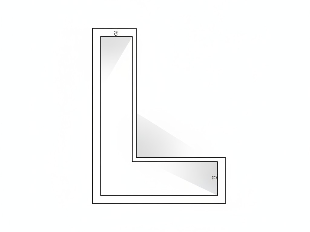
This approach works because it covers both entries. As soon as you step into the hallway from either end, the local sensor catches you. By the time you walk around the blind corner, the second sensor picks you up, keeping the timer active. It creates a seamless handover.
人感センサーを活用した省エネソリューションをお探しですか?
PIR人感センサー、人感センサー搭載省エネ製品、人感センサースイッチ、商業施設向けOccupancy/Vacancy(在室/不在)ソリューションについては、お気軽にお問い合わせください。
The “No-Neutral” Trap
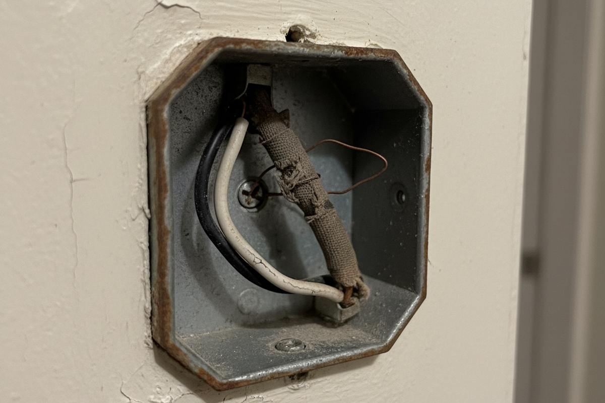
While we’re discussing wiring, we need to address the “No-Neutral” option. Many older homes (pre-1980s) don’t have a bundle of white neutral wires in the switch box. Manufacturers know this, so they sell “No-Neutral Required” sensors (often denoted with an -N suffix).
Avoid these unless you have absolutely no choice.
To function without a neutral, the sensor has to trickle a tiny amount of current through the light bulb itself to stay powered up. This is called “leakage current.” In the days of incandescent bulbs, this was fine; the filament didn’t care. But with modern LED wafers or low-wattage bulbs, that tiny current is often enough to charge the capacitors in the LED driver.
The result? “Ghosting” (the light glows faintly when off) or flickering. You’ll get a call a week later saying the hallway lights are strobing like a disco. If you open the box and see a bundle of white wires tucked in the back, use the standard 3-wire sensor (Hot, Neutral, Load). It provides a clean, stable return path for the sensor’s electronics and eliminates the ghosting issue entirely.
Final Simulation: Don’t Just Crank the Time
Finally, don’t try to fix a placement problem with a settings change. I see this constantly: the sensor is in a blind spot, so the installer cranks the timeout dial to “30 Minutes.” The logic is, “If it stays on for a long time, it won’t turn off while they are walking in the shadow.”
This defeats the purpose of the sensor. You’re just installing a very expensive, annoying light switch that wastes electricity.
Before you screw the faceplate on, do a real walk-test. Set the time delay to the minimum (usually 15 seconds or “Test Mode”). Walk the path. Walk from the bedroom to the kitchen. Walk from the living room to the bathroom. See exactly where the light triggers. If you can take three steps in the dark before it fires, adjust the sensitivity or the angle. If you can’t fix it with angle, you need to move the box or add a second sensor. Don’t leave the site until the geometry works.