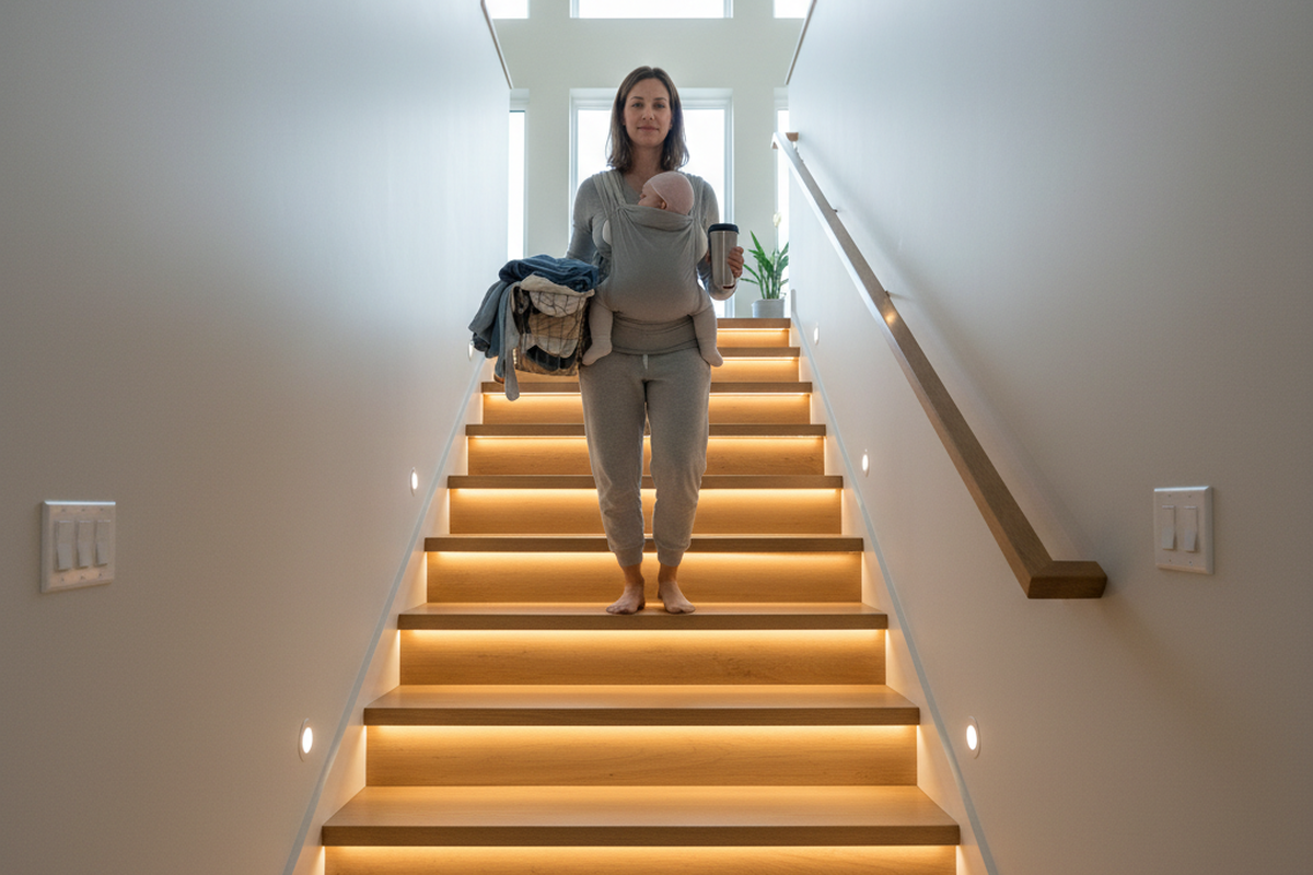
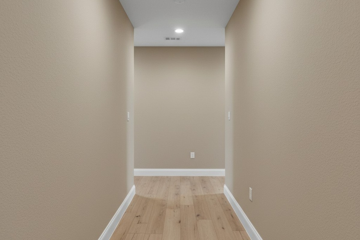
You’ve likely seen this in a commercial building, or maybe even your own hallway. You walk out of a bedroom, hands full of laundry or groceries, into the dark. You take three steps toward the kitchen, expecting the motion sensor to catch you, but the hallway stays pitch black. You have to walk another ten feet, almost to the end of the hall, before the lights finally snap on. Or worse, you find yourself doing the “waving arms” dance in the dark, hoping to catch the sensor’s attention.
This is a geometry failure, not just a nuisance. It happens because someone treated an L-shaped hallway like a straight line. They swapped out an existing switch for a motion sensor, assumed the “180-degree field of view” on the box was magic, and called it a day. But physics doesn’t care about your convenience, and infrared heat signatures can’t bend around drywall. If the sensor can’t see you, the lights stay off. It’s that simple.
Why the L-Shape Defeats Standard PIR
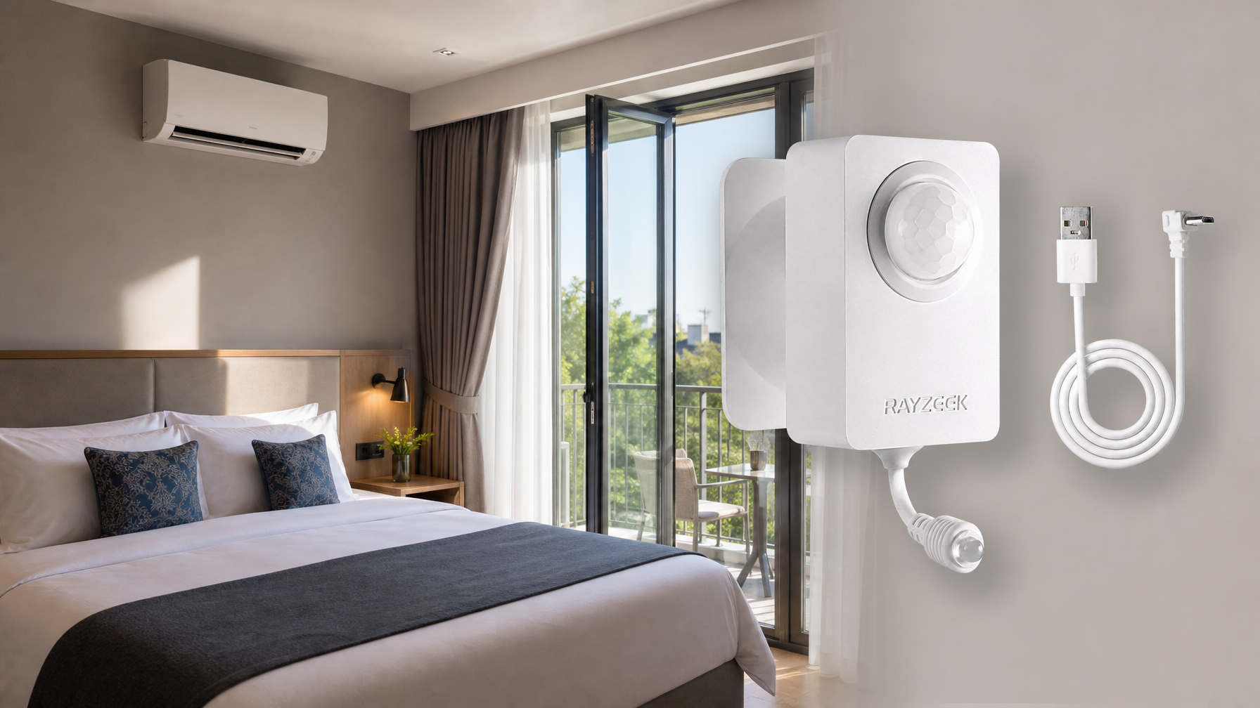
To fix this, you have to understand what the sensor is actually doing. Most residential sensors, including the Rayzeek RZ series, use Passive Infrared (PIR) technology. They look for a heat differential moving across a Fresnel lens.
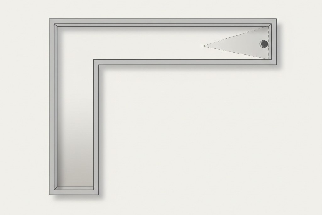
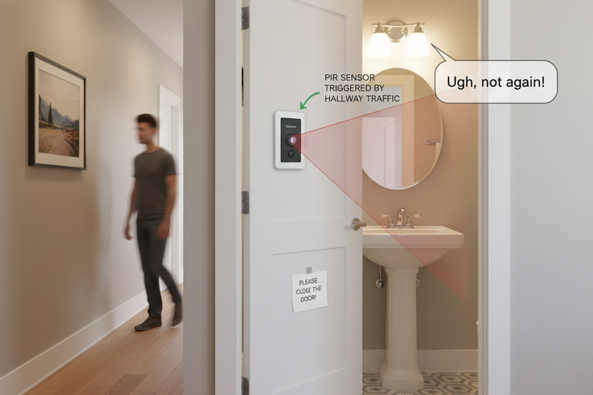
Think of the sensor like a flashlight beam. If you taped a flashlight to the switch box, where would the light hit? In an L-shaped hallway, usually with switch boxes at the far ends of the “legs,” that beam hits the opposite wall and stops. The other leg of the hallway stays in shadow.
There’s a misconception that these sensors work like radar or sonar, bouncing signals around corners. They don’t. (Ultrasonic sensors exist, mostly in commercial bathrooms, but they’re overkill for a house and prone to false triggers every time the HVAC kicks on). For a standard PIR switch, line-of-sight is non-negotiable. If you’re standing in the “shadow” of the corner—the area the lens physically can’t see—you don’t exist to the system.
This is also why “pet immunity” is such a headache in these layouts. People try to mask the bottom of the lens to avoid the cat triggering the lights at 3 AM, which further narrows the vertical detection cone. If you have bad horizontal placement 및 you tape off the bottom of the lens, you’ve effectively built a light switch that requires you to stand directly in front of it and wave.
So, how do you solve the blind corner? You have two options: a carpenter’s solution (moving the device) or an electrician’s solution (wiring a network).
Strategy 1: The Fulcrum Mount (The Carpenter’s Fix)
In many retrofits—specifically in older farmhouses or renovations where the layout is quirky—the existing switch boxes are in the worst possible spots, usually at the far ends of the hallway. If you install a sensor at the end of the hall, it only sees down one leg. The most robust fix is often to ignore the electrical boxes you have and cut in a new one where you actually need it.
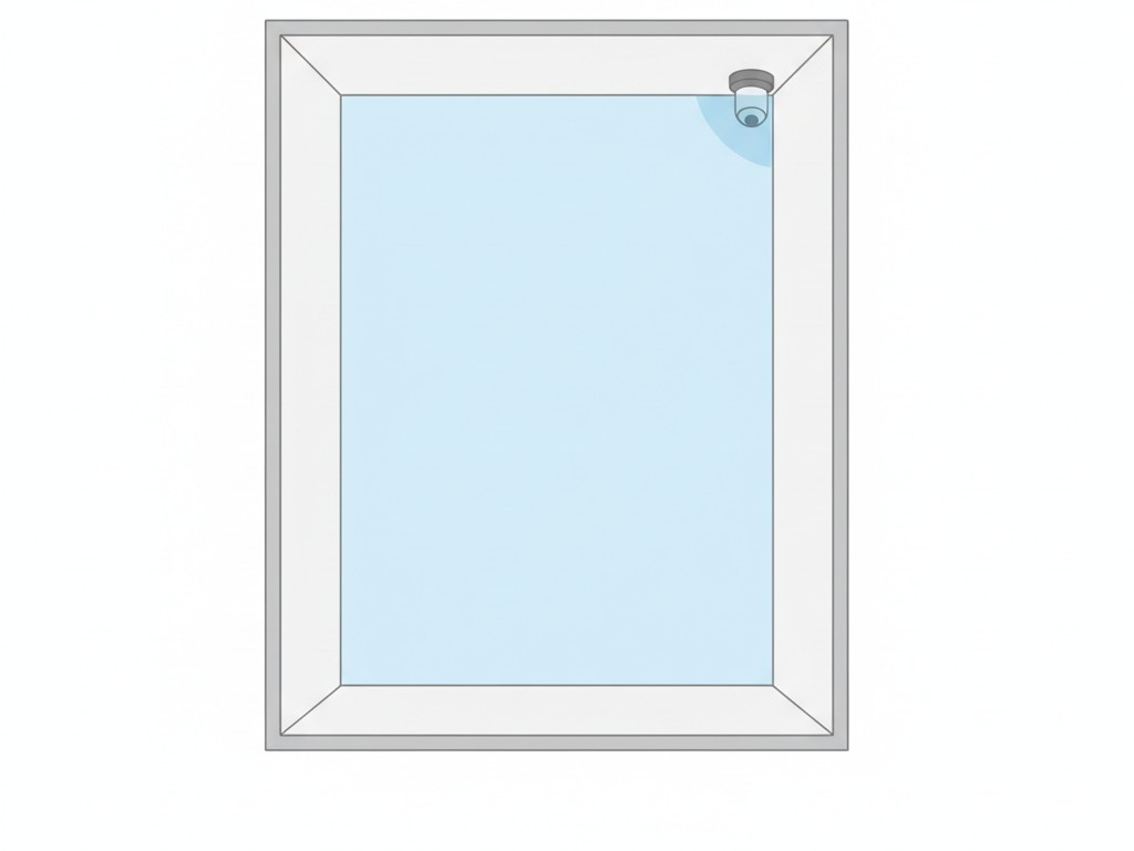
We call this the Fulcrum Strategy. You identify the outer corner of the “L”—the vertex where the two hallways meet. If you place a wide-angle sensor (like the Rayzeek RZ021) on that corner, usually ceiling-mounted or high on the wall, it has a clear shot down both legs of the hallway. It’s the sniper’s perch of motion detection.
관심 있는 다른 제품

- 전압: AAA 배터리 2개
- 주간/야간 모드
- 시간 지연: 15분, 30분, 1시간(기본값), 2시간
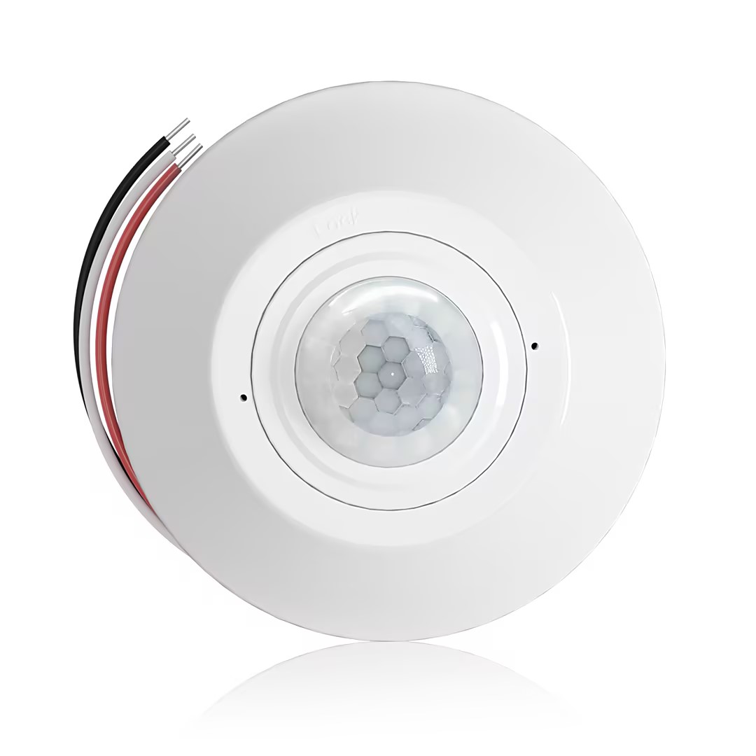
- 무전압 접점 리레이 출력을 갖춘 천장 설치형 PIR 재실 감지 센서
- 12/24VDC 또는 12/24VAC 저전압 전원 공급
- EMS, HVAC 및 빌딩 제어 입력을 위한 COM, NO 및 NC 절연 리레이 접점
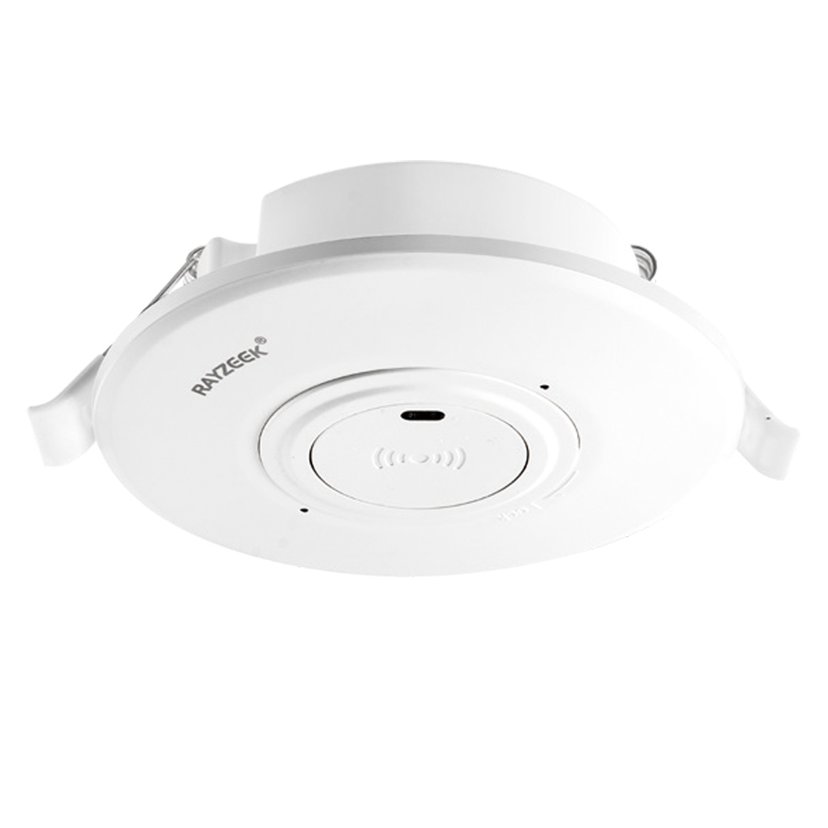
- 저전압 DC 매립형 천장 설치형 마이크로웨이브 모션 센서 스위치
- 10-30 VDC 범위를 지원하는 12 VDC / 24 VDC 입력
- 조절 가능한 지연 시간, Lux 임계값 및 감도 기능을 갖춘 최대 10A 동작 전류
- 고부하용 매립형 천장 설치형 마이크로웨이브 모션 센서 스위치
- 100-265 VAC 라인 전압 입력, 10A 모델
- 조절 가능한 지연 시간, Lux 임계값 및 감도를 갖춘 5.8 GHz 마이크로웨이브 감지
- 천장 매립형 마이크로웨이브 동작 감지 센서 스위치
- 100-265 VAC 라인 전압 입력, 5A 모델
- 조절 가능한 지연 시간, Lux 임계값 및 감도를 갖춘 5.8 GHz 마이크로웨이브 감지
- 220V 전원용 천장 부착형 RZ037 PIR 재실 감지 센서 디머
- 660W 정격 부하 및 최대 동작 전류 3A
- LUX 버튼으로 조도 센서 ON/OFF 및 사용자 설정 디밍 밝기 제어
- 110V 전원용 천장 부착형 RZ037 PIR 재실 감지 디머 스위치
- 330W 정격 부하 및 최대 동작 전류 3A
- LUX 버튼으로 조도 센서 ON/OFF 및 사용자 설정 디밍 밝기 제어
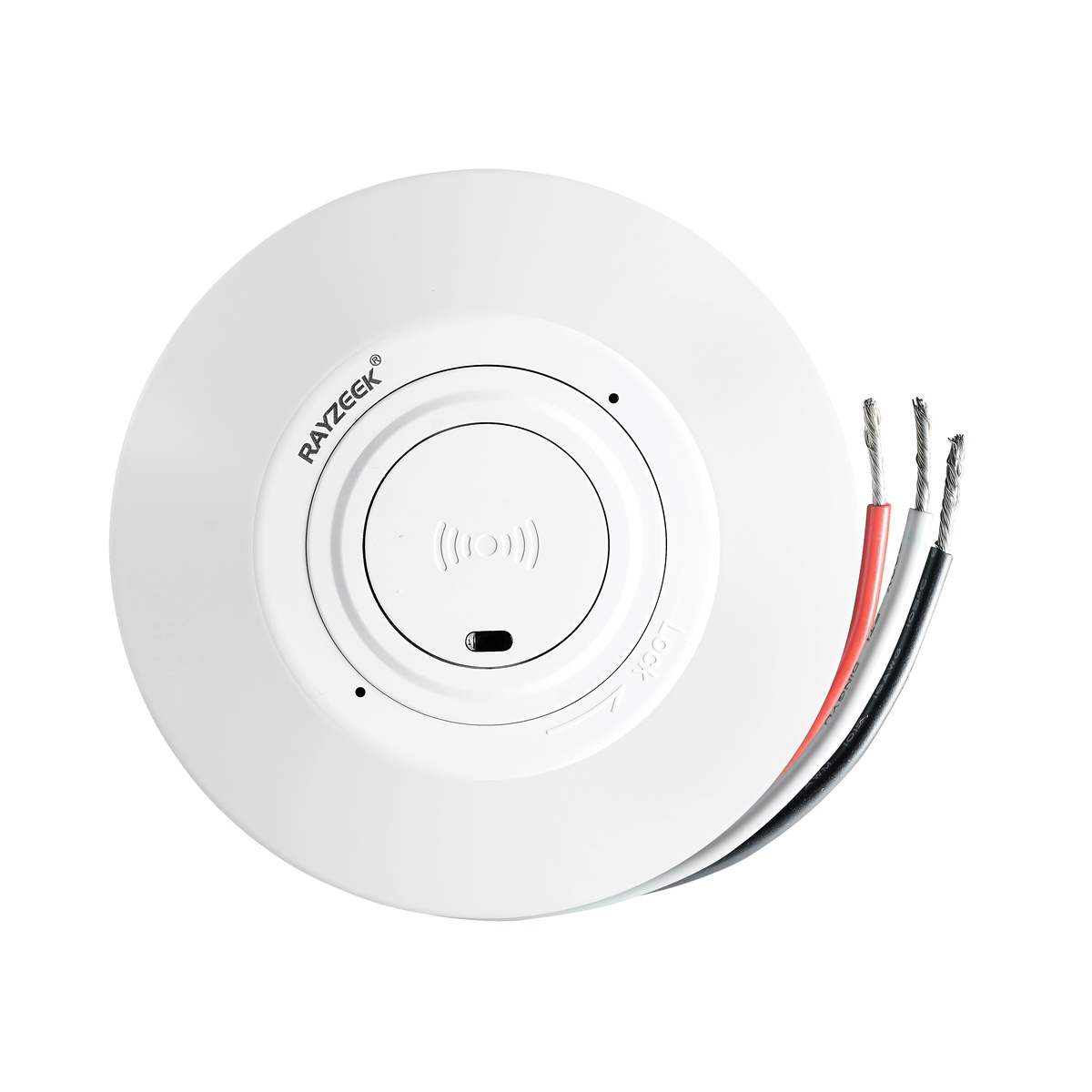
- 저전압 DC 천장 부착형 마이크로웨이브 동작 감지 센서 스위치
- 10-30 VDC 범위를 지원하는 12 VDC / 24 VDC 입력
- 조절 가능한 지연 시간, Lux 임계값 및 감도 기능을 갖춘 최대 10A 동작 전류
- 고부하용 천장 부착형 마이크로웨이브 동작 감지 센서 스위치
- 100-265 VAC 라인 전압 입력, 10A 모델
- 조절 가능한 지연 시간, Lux 임계값 및 감도를 갖춘 5.8 GHz 마이크로웨이브 감지
- 천장 부착형 마이크로웨이브 동작 감지 센서 스위치
- 100-265 VAC 라인 전압 입력, 5A 모델
- 조절 가능한 지연 시간, Lux 임계값 및 감도를 갖춘 5.8 GHz 마이크로웨이브 감지
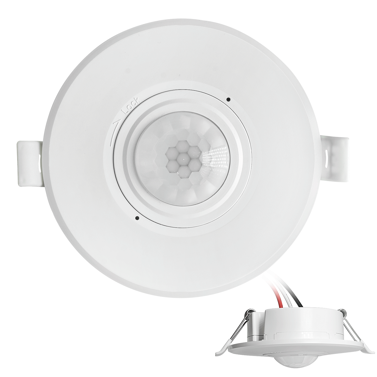
- 저전압 DC 매립형 천장 PIR 동작 감지 센서 스위치
- 10-30 VDC 범위를 지원하는 12 VDC / 24 VDC 입력
- 시간 지연, 조도 임계값, 감도 조절이 가능한 최대 동작 전류 10A 제품
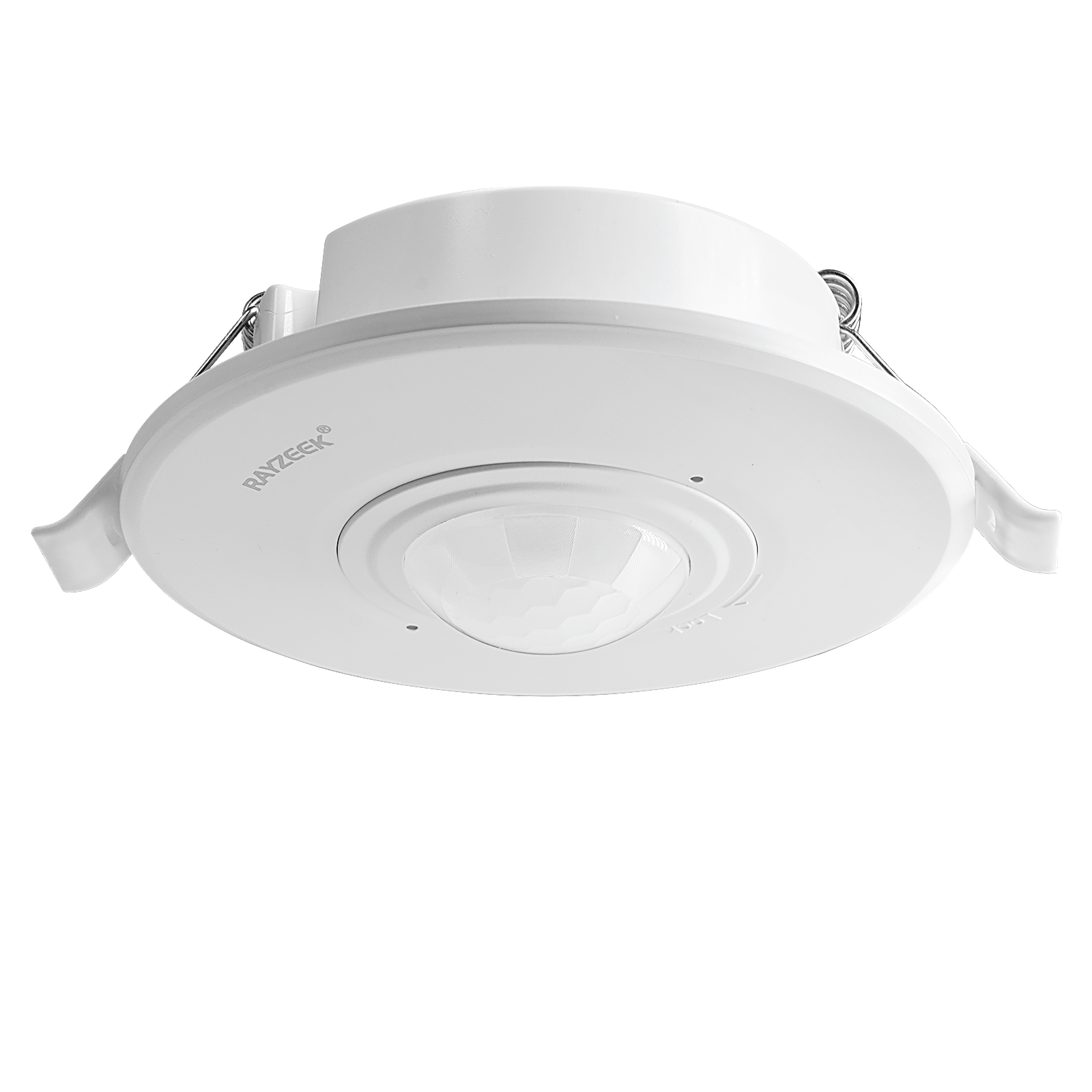
- 고부하용 매립형 천장 PIR 동작 감지 센서 스위치
- 100-265 VAC 라인 전압 입력, 10A 모델
- 시간 지연, 조도 임계값, 감도 조절이 가능한 360도 감지
- 매립형 천장 PIR 동작 감지 센서 스위치
- 100-265 VAC 라인 전압 입력, 5A 모델
- 시간 지연, 조도 임계값, 감도 조절이 가능한 360도 감지
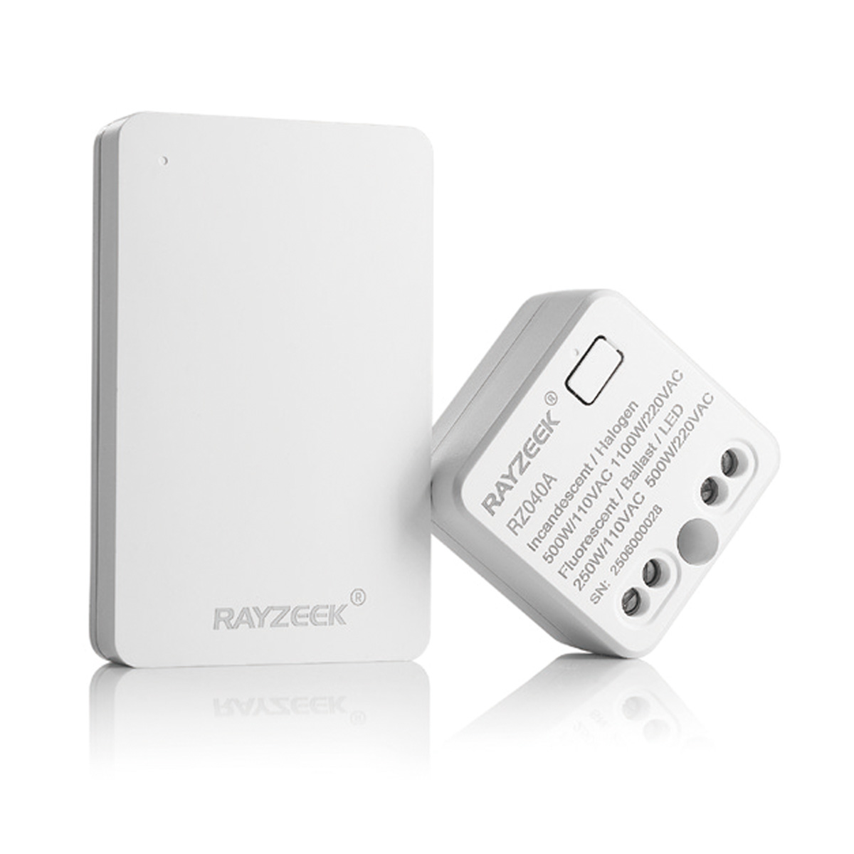
- 실내 ON/OFF 조명 제어용 무선 스위치 및 수신기 키트
- 정격 전류 5A의 100-230VAC, 50/60Hz 수신기
- 2.4GHz 통신 방식의 CR2032 배터리 구동 무선 스위치
- 재실 모드(자동 ON/자동 OFF)
- 12–24V DC (10–30VDC), 최대 10A
- 360° 감지 범주, 직경 8–12m
- 시간 지연 15초–30분
- 조도 센서 Off/15/25/35 Lux
- 높음/낮음 감도
- 자동 ON/자동 OFF 재실 모드
- 100–265V AC, 10A (중성선 필요)
- 360° 감지 범위; 감지 직경 8–12m
- 시간 지연 15초–30분; 조도 OFF/15/25/35; 감도 높음/낮음
- 자동 ON/자동 OFF 재실 모드
- 100–265V AC, 5A (중성선 필요)
- 360° 감지 범위; 감지 직경 8–12m
- 시간 지연 15초–30분; 조도 OFF/15/25/35; 감도 높음/낮음
This requires getting your hands dirty. You’ll need a “cut-in” or “old work” box (like the blue Carlon boxes with the flip-out wings), a drywall saw, and a fish tape. You pull the line voltage from one of the existing switch locations, snake it through the ceiling or attic, and drop it down to this new corner location. You then blank off the old switches or turn them into permanent power feeds.
It sounds like more work, but run the math on the callback cost. Spending an hour fishing a wire and patching a small square of drywall is cheaper than buying wireless battery-powered sensors that fail every six months, or coming back three times because the client is complaining about the lights not turning on. With the sensor at the fulcrum, the geometry problem is solved instantly. One device, 100% coverage, zero blind spots.
Strategy 2: The Wired 3-Way (The Electrician’s Fix)
If you can’t cut into the drywall—maybe it’s a condo with concrete walls or a high-end finish you can’t touch—you have to use the existing box locations. This means you need two sensors, one at each end of the L, working together. This is where most installations go wrong because people assume a motion sensor wires up exactly like a mechanical 3-way switch. It doesn’t.
In a standard mechanical 3-way, the switches toggle power back and forth along “traveler” wires. If you just swap those mechanical switches for sensors, you often end up with a system where one sensor kills power to the other, or they fight for control. The lights might strobe, or one end of the hall will work while the other is dead.
For Rayzeek units (and similar hardwired sensors), you typically wire them in parallel or use a specific “3-way” model that communicates via a traveler. The goal is that if 둘 중 어느 하나라도 sensor triggers, the load (the light) gets power.
There is a massive point of confusion here for anyone who has just browsed a forum: don’t confuse “multi-location dimming” logic with motion sensor logic. You aren’t trying to dim the lights from both ends; you’re just trying to close the circuit.
Rayzeek 모션 센서 포트폴리오에서 영감을 얻어보세요.
원하시는 제품을 찾지 못하셨나요? 걱정하지 마세요. 문제를 해결할 수 있는 대체 방법은 언제나 존재합니다. 당사의 포트폴리오 중 하나가 도움이 될 수 있습니다.
When you wire this, you usually tie the “Line” (hot) wire to both sensors. You tie the “Load” wire (the one going to the light) to the output of both sensors. This creates a logical “OR” gate: if Sensor A sees motion OR Sensor B sees motion, the light turns on.
Note: Always check the specific schematic for your model (e.g., RZ021 vs RZ023). Some newer models require a dedicated traveler wire for communication, and the color of that wire in the box can vary by batch—sometimes it’s yellow, sometimes it’s a striped red. Don’t guess.
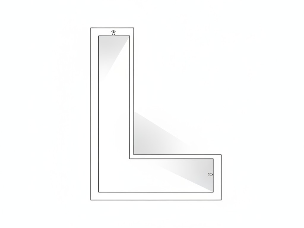
This approach works because it covers both entries. As soon as you step into the hallway from either end, the local sensor catches you. By the time you walk around the blind corner, the second sensor picks you up, keeping the timer active. It creates a seamless handover.
동작 감지 기반의 에너지 절감 솔루션을 찾고 계십니까?
PIR 동작 감지 센서, 동작 감지 에너지 절감 제품, 동작 감지 센서 스위치, 상업용 점유/부재(Occupancy/Vacancy) 감지 솔루션에 대해 문의해 주시기 바랍니다.
The “No-Neutral” Trap
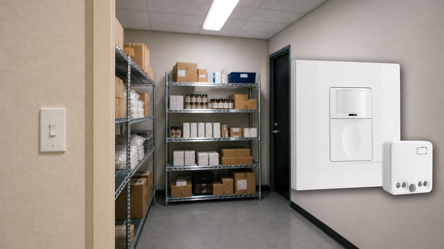
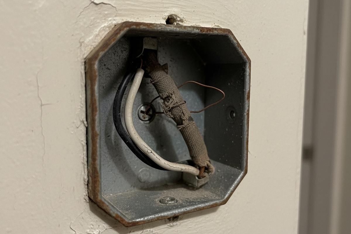
While we’re discussing wiring, we need to address the “No-Neutral” option. Many older homes (pre-1980s) don’t have a bundle of white neutral wires in the switch box. Manufacturers know this, so they sell “No-Neutral Required” sensors (often denoted with an -N suffix).
Avoid these unless you have absolutely no choice.
To function without a neutral, the sensor has to trickle a tiny amount of current through the light bulb itself to stay powered up. This is called “leakage current.” In the days of incandescent bulbs, this was fine; the filament didn’t care. But with modern LED wafers or low-wattage bulbs, that tiny current is often enough to charge the capacitors in the LED driver.
The result? “Ghosting” (the light glows faintly when off) or flickering. You’ll get a call a week later saying the hallway lights are strobing like a disco. If you open the box and see a bundle of white wires tucked in the back, use the standard 3-wire sensor (Hot, Neutral, Load). It provides a clean, stable return path for the sensor’s electronics and eliminates the ghosting issue entirely.
Final Simulation: Don’t Just Crank the Time
Finally, don’t try to fix a placement problem with a settings change. I see this constantly: the sensor is in a blind spot, so the installer cranks the timeout dial to “30 Minutes.” The logic is, “If it stays on for a long time, it won’t turn off while they are walking in the shadow.”
This defeats the purpose of the sensor. You’re just installing a very expensive, annoying light switch that wastes electricity.
Before you screw the faceplate on, do a real walk-test. Set the time delay to the minimum (usually 15 seconds or “Test Mode”). Walk the path. Walk from the bedroom to the kitchen. Walk from the living room to the bathroom. See exactly where the light triggers. If you can take three steps in the dark before it fires, adjust the sensitivity or the angle. If you can’t fix it with angle, you need to move the box or add a second sensor. Don’t leave the site until the geometry works.