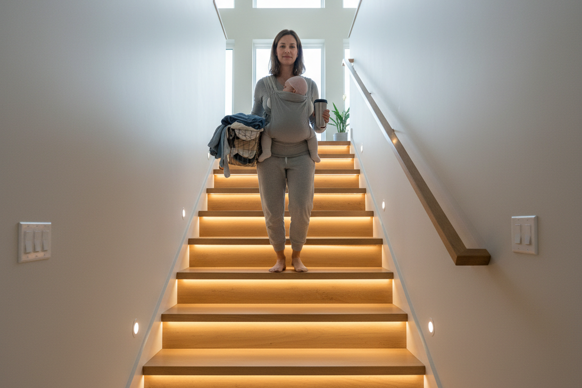
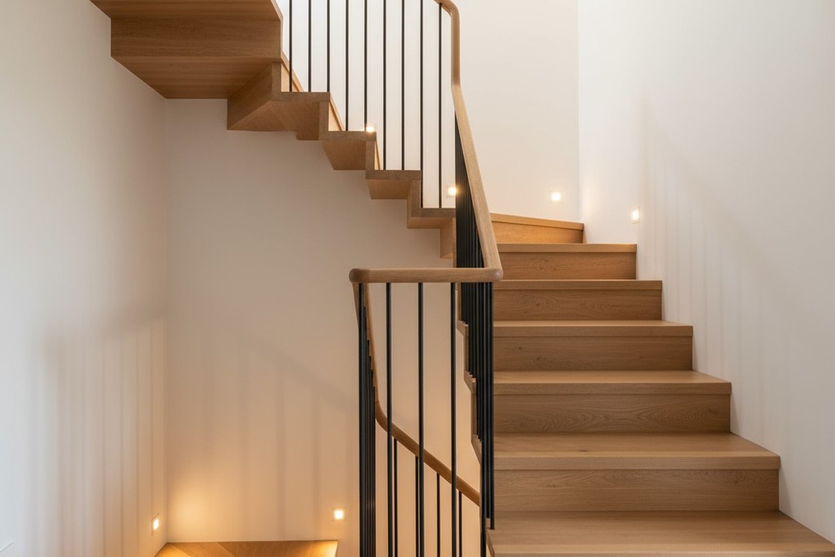
The staircase is a space of constant motion, but automating its lighting often creates an electrical nightmare. Instead of smooth, reliable light, you get the “stair strobe”—a flickering, unpredictable mess where lights flash as someone walks up the stairs or refuse to respond to one of the switches.
This isn’t a faulty motion sensor. It’s a faulty wiring plan. A standard 3-way circuit was designed for simple mechanical switches, and dropping a smart sensor into that old design without a strategy is asking for trouble. A clean, reliable system requires a new approach that establishes a clear hierarchy of control.
The Traveler Wire Conflict: Why Old 3-Way Circuits Fight Automation
A conventional 3-way circuit is a clever design for controlling one light from two spots. It uses two “traveler” wires running between the switches. Think of the switches as track changers for electricity. Flipping either switch breaks one electrical path and completes another, turning the light on or off.
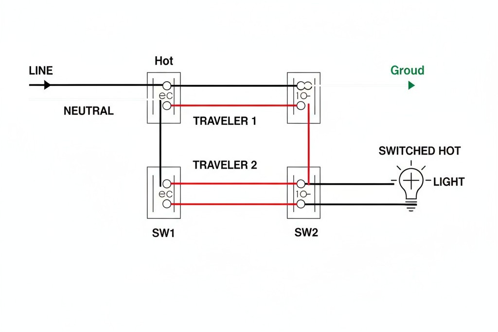
The design is simple, but it has a fatal flaw for automation: at any given moment, only one of the two traveler wires is live. A motion sensor, being an electronic device, needs a constant supply of power for its internal brain. It can’t function if its own power source is being cut by a second switch down the hall. When you install a sensor in a traditional 3-way setup, the sensor and the mechanical switch end up fighting for control, creating the erratic behavior that plagues so many projects.
從 Rayzeek 動態感測器產品組合中獲得靈感。
找不到您想要的產品?別擔心。總有其他方法可以解決您的問題。也許我們的其中一個產品組合可以幫到您。
The Point of Command: Why the Sensor Goes in the Line-Side Box
To build a stable smart circuit, one device must have the final say. The motion sensor needs to be the primary controller, deciding when the circuit gets power. The second switch simply becomes a way to send a “request” to the sensor. For this to work, the sensor must be installed where the power enters the circuit.
In any 3-way setup, one electrical box contains the “line” wire from the breaker panel, and the other contains the “load” wire running to the light fixture. By placing the Rayzeek sensor in the line-side box, you position it to manage all incoming power. It can power itself reliably and then decide whether to send electricity on to the light, based on motion or a signal from the other switch. This architecture transforms a power struggle into an orderly system with a clear chain of command.
Finding the Power Source: The First Step
Before you touch a single wire, you have to find the line-side box. First, kill the power to the circuit at the breaker panel.
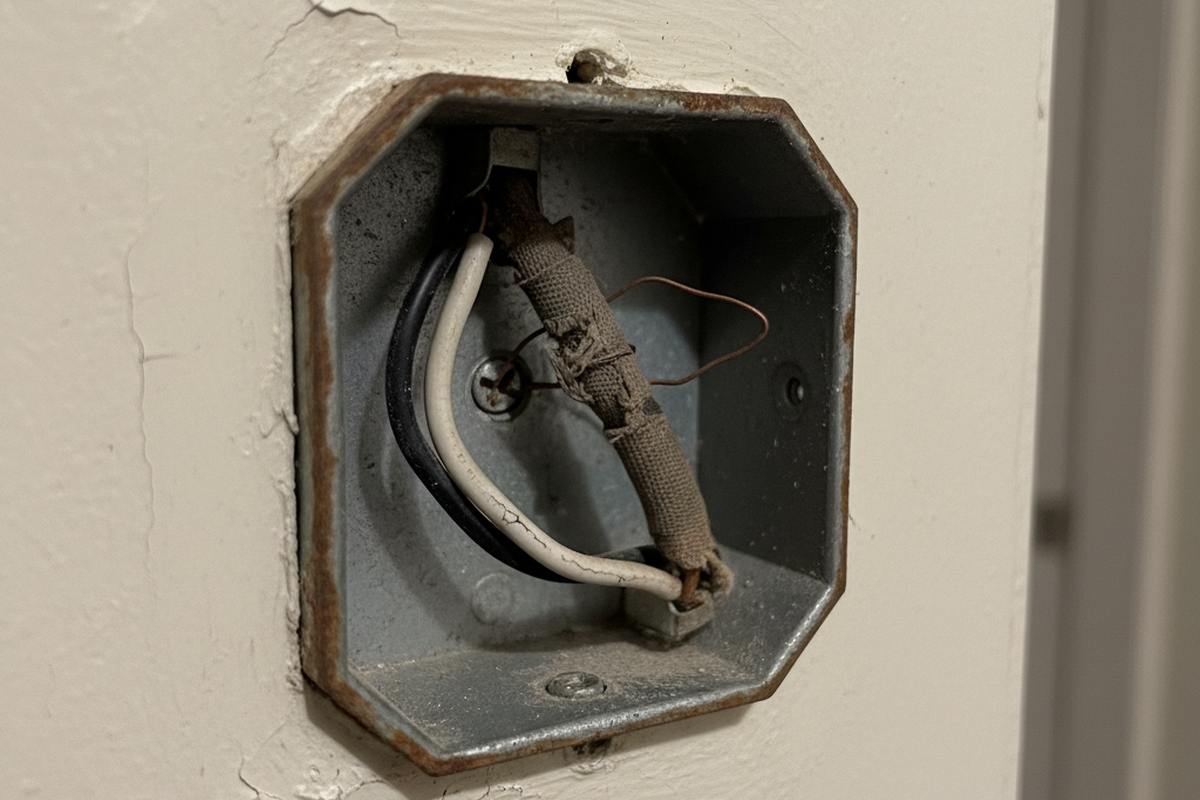
With the circuit de-energized, remove both wall plates and pull the switches from their boxes, leaving the wires attached for now. Make sure no bare wires are touching each other or any metal. Now, go back and turn the breaker on. Using a non-contact voltage tester, carefully check the wires at each switch. In one box, a single wire (usually black) will be hot. That’s your line-side box, where the Rayzeek sensor will go. The other box, where no wires are live, is the load-side box. Once you’ve found it, turn the power off at the breaker again before you do anything else.
The Definitive Wiring Pattern
With the power off and the line-side box identified, you can rewire the circuit. This pattern repurposes one of the traveler wires as a dedicated communication link.
正在尋找動態感應節能解決方案?
歡迎聯絡我們以獲取完整的 PIR 動態感應器、動態感應節能產品、動態感應器開關以及人體感應/無人感應商業解決方案。
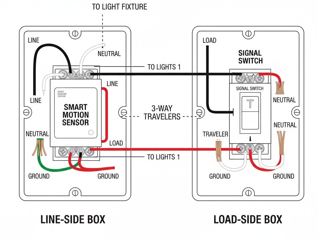
In the Line-Side Box (Sensor): The Rayzeek sensor goes here.
- Connect the black “line” wire (the one you identified as hot) to the sensor’s Line terminal.
- Bundle the white neutral wires in the box with the sensor’s Neutral wire.
- Connect the ground wires to the sensor’s ground screw. This provides the constant power the sensor needs.
- Choose one traveler wire (often red) to be your signal wire. Connect it to the sensor’s Traveler (or signal) terminal.
- Connect the second traveler wire to the sensor’s Load terminal. This wire will now carry switched power to the light.
In the Load-Side Box (Switch): A standard 3-way switch goes here, but its job is simpler.
- Find the traveler wire coming from the sensor’s Load terminal. Connect this directly to the wire running to the light fixture, bypassing the switch entirely.
- Find the other traveler (your signal wire). Connect it to the common (dark-colored) screw on the 3-way switch.
- Connect the remaining traveler terminal on the switch back to a hot source to complete the signaling circuit, following your sensor’s specific diagram. This switch no longer controls the light directly; it only sends a signal to the sensor.
Stop the Strobe: Set a Longer Timeout
With the wiring done, the final tweak is in the sensor’s settings. The “stair strobe” is almost always caused by a timeout delay that’s too short. If the delay is set to one minute, the lights can switch off while someone is still on the stairs, only to be instantly re-triggered, causing that jarring flash.
您可能也會感興趣

- 電壓:2 粒 AAA 電池
- 日/夜模式
- 延遲時間:15 分鐘、30 分鐘、1 小時(預設)、2 小時
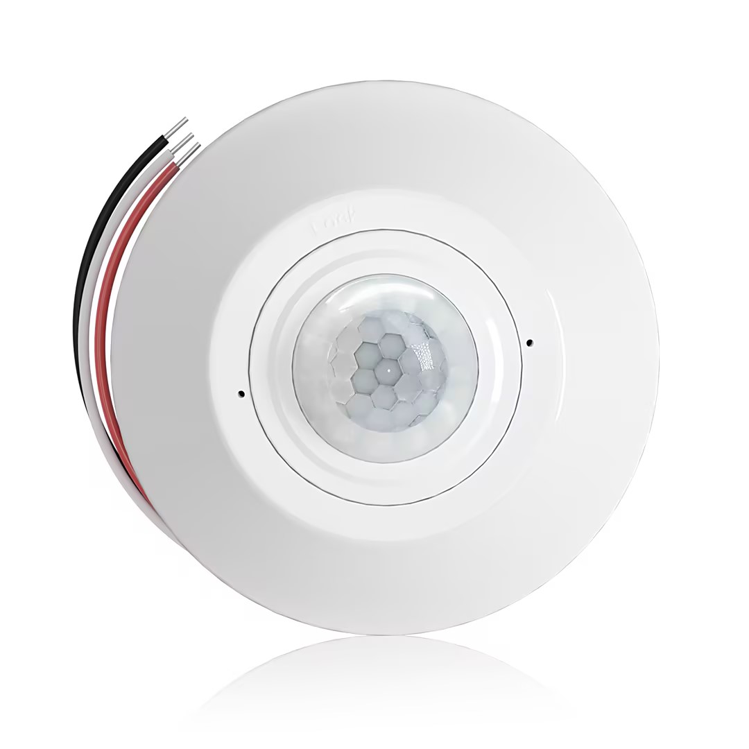
- 吸頂式 PIR 人體感應器,配備乾觸點繼電器輸出
- 12/24VDC 或 12/24VAC 低電壓供電
- 用於 EMS、HVAC 和建築控制輸入的 COM、NO 和 NC 隔離繼電器觸點
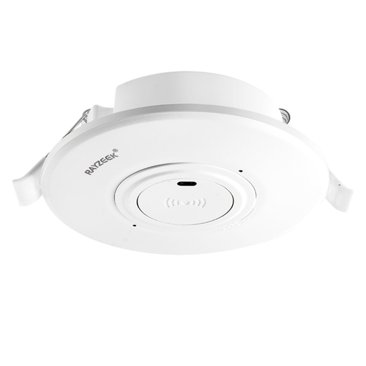
- 低壓直流嵌入式天花安裝微波人體感應開關
- 12 VDC / 24 VDC 輸入,支援 10-30 VDC 範圍
- 最大工作電流 10A,配備可調節延時、光感閾值及靈敏度
- 高負載嵌入式天花安裝微波人體感應開關
- 100-265 VAC 市電輸入,10A 型號
- 5.8 GHz 微波感應,配備可調節延時、光感閾值及靈敏度
- 嵌入式天花安裝微波人體感應開關
- 100-265 VAC 市電輸入,5A 型號
- 5.8 GHz 微波感應,配備可調節延時、光感閾值及靈敏度
- 適用於 220V 電源的天花安裝 RZ037 PIR 被動式紅外線佔空感應調光開關
- 最大工作電流 3A,額定負載 660W
- LUX 按鈕控制光線感應器開關及用戶設定之調光亮度
- 適用於 110V 電源的天花安裝 RZ037 PIR 被動式紅外線佔空感應調光開關
- 最大工作電流 3A,額定負載 330W
- LUX 按鈕控制光線感應器開關及用戶設定之調光亮度
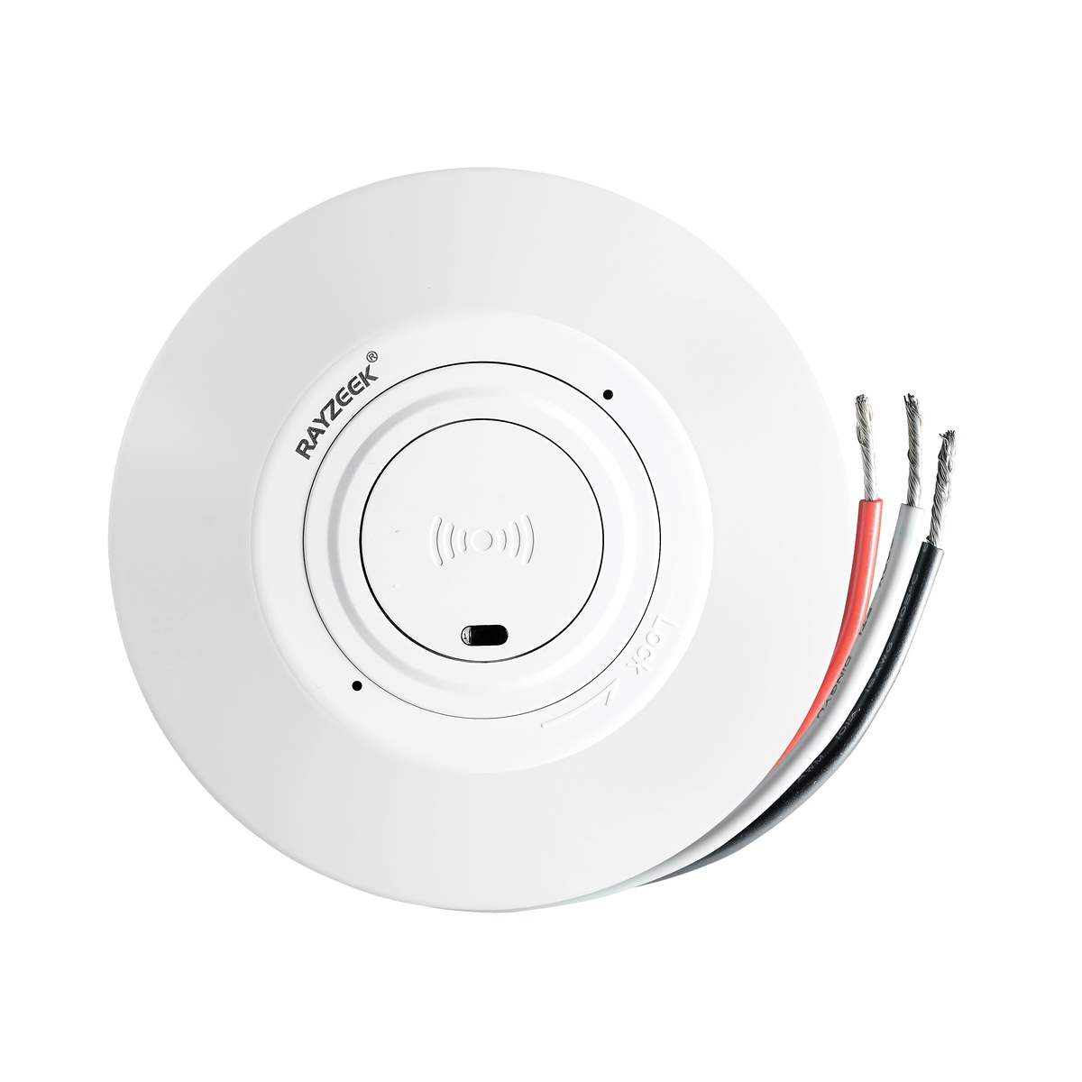
- 低壓直流天花安裝微波人體感應開關
- 12 VDC / 24 VDC 輸入,支援 10-30 VDC 範圍
- 最大工作電流 10A,配備可調節延時、光感閾值及靈敏度
- 高負載吸頂式微波動態感應器開關
- 100-265 VAC 市電輸入,10A 型號
- 5.8 GHz 微波感應,配備可調節延時、光感閾值及靈敏度
- 吸頂式微波動態感應器開關
- 100-265 VAC 市電輸入,5A 型號
- 5.8 GHz 微波感應,配備可調節延時、光感閾值及靈敏度
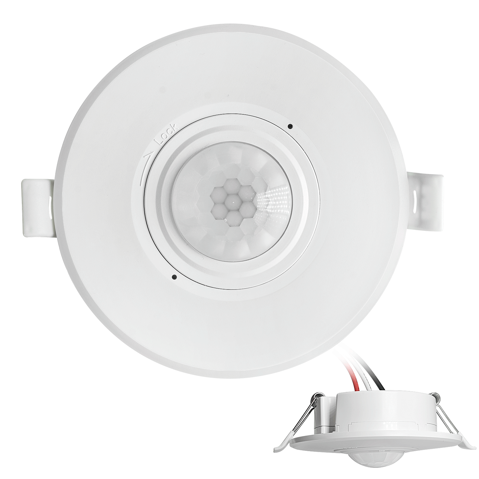
- 低壓直流嵌頂式 PIR 動態感應器開關
- 12 VDC / 24 VDC 輸入,支援 10-30 VDC 範圍
- 最大工作電流 10A,具備可調式時間延遲、光照度閾值及靈敏度
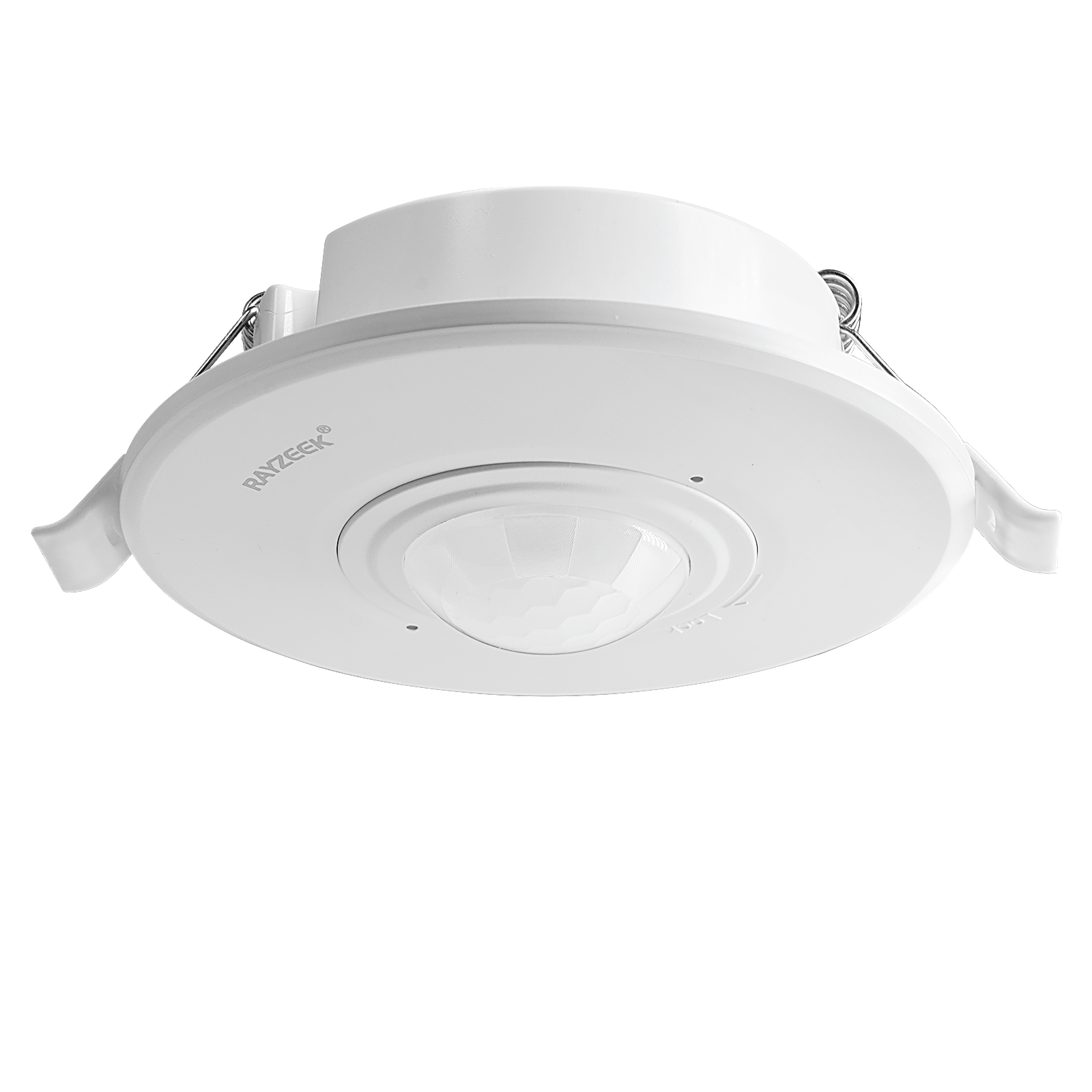
- 高負載嵌頂式 PIR 動態感應器開關
- 100-265 VAC 市電輸入,10A 型號
- 360度偵測,具備可調式時間延遲、光照度閾值及靈敏度
- 嵌頂式 PIR 動態感應器開關
- 100-265 VAC 市電輸入,5A 型號
- 360度偵測,具備可調式時間延遲、光照度閾值及靈敏度
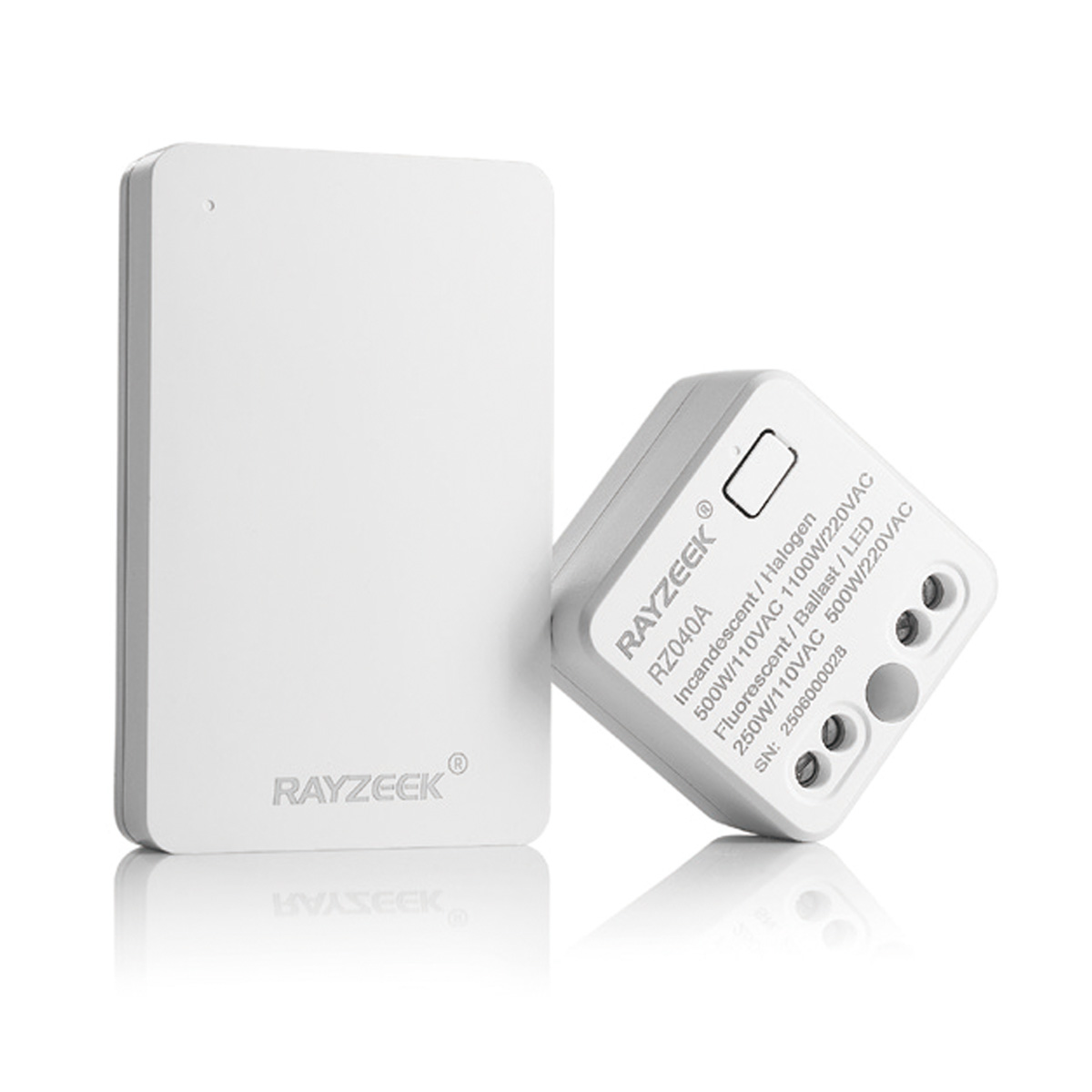
- 用於室內開關照明控制的無線開關及接收器套裝
- 100-230VAC,50/60Hz 接收器,額定電流 5A
- CR2032 電池供電無線開關,採用 2.4GHz 通訊
- 佔用感應(自動開啟/自動關閉)
- 12–24V DC (10–30VDC),最高 10A
- 360° 覆蓋,直徑 8–12 米
- 延遲時間 15 秒至 30 分鐘
- 光感應器 關閉/15/25/35 Lux
- 高/低靈敏度
- 自動開啟/自動關閉佔用模式
- 100–265V AC,10A(需接零線)
- 360° 全方位覆蓋;8–12 米偵測直徑
- 延遲時間 15 秒至 30 分鐘;Lux 關閉/15/25/35;靈敏度 高/低
- 自動開啟/自動關閉佔用模式
- 100–265V AC,5A(需接零線)
- 360° 全方位覆蓋;8–12 米偵測直徑
- 延遲時間 15 秒至 30 分鐘;Lux 關閉/15/25/35;靈敏度 高/低
For staircases and long hallways, a longer timeout is crucial. Set the Rayzeek sensor’s time delay to at least three to five minutes. This ensures the light stays on for the entire trip between floors, turning a flickering problem area into a smoothly, reliably lit path.
Built to Work
Fixing a 3-way circuit isn’t about finding a clever hack. It’s about implementing a wiring pattern that respects how electricity actually works. By giving the sensor primary control at the line-side box, you create the robust, stable system that defines professional automation. This pattern is designed to do one job perfectly: control a light with absolute reliability, ending the stair strobe for good.