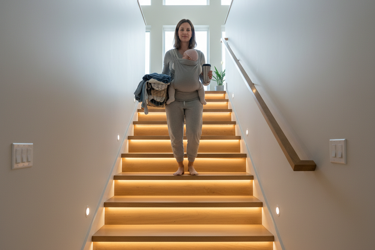
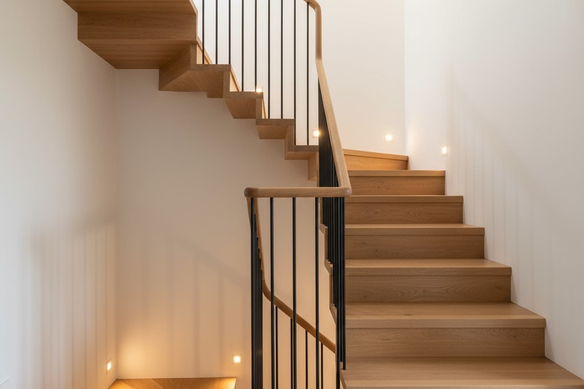
A escadaria é um espaço de movimento constante, mas automatizar a sua iluminação cria frequentemente um pesadelo elétrico. Em vez de uma luz suave e fiável, obtém o “estroboscópio de escada” — uma confusão oscilante e imprevisível na qual as luzes piscam quando alguém sobe as escadas ou recusam-se a responder a um dos interruptores.
Isto não é um sensor de movimento com defeito. É um plano de cablagem com defeito. Um circuito de 3 vias padrão foi concebido para interruptores mecânicos simples, e colocar um sensor inteligente nesse projeto antigo sem uma estratégia é procurar problemas. Um sistema limpo e fiável exige uma nova abordagem que estabeleça uma hierarquia de controlo clara.
O conflito do fio condutor: por que os circuitos antigos de 3 vias combatem a automação
Um circuito convencional de 3 vias é uma conceção inteligente para controlar uma luz a partir de dois pontos. Utiliza dois fios “condutores” que passam entre os interruptores. Pense nos interruptores como comutadores de linha para a eletricidade. Alternar qualquer um dos interruptores interrompe um caminho elétrico e completa outro, ligando ou desligando a luz.
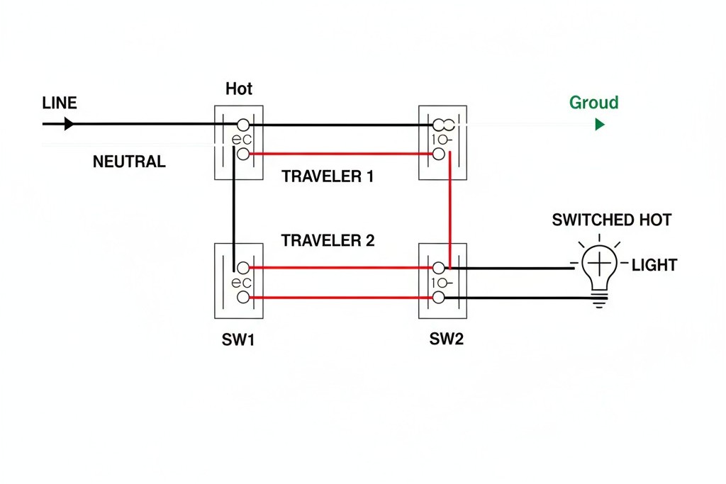
A conceção é simples, mas tem uma falha fatal para a automação: em qualquer momento, apenas um dos dois fios condutores está sob tensão. Um sensor de movimento, sendo um dispositivo eletrónico, necessita de um fornecimento constante de energia para o seu cérebro interno. Não pode funcionar se a sua própria fonte de alimentação for cortada por um segundo interruptor no fundo do corredor. Quando instala um sensor numa configuração tradicional de 3 vias, o sensor e o interruptor mecânico acabam por disputar o controlo, criando o comportamento errático que afeta tantos projetos.
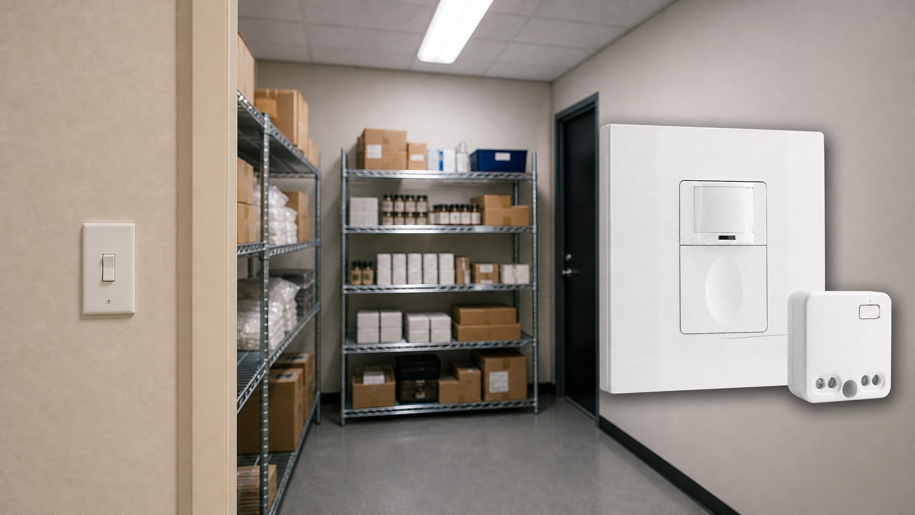
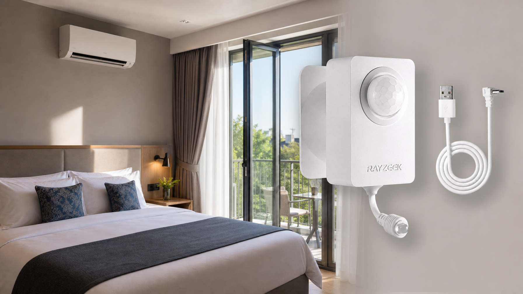
Inspire-se com os portfólios de sensores de movimento da Rayzeek.
Não encontra o que pretende? Não se preocupe. Existem sempre formas alternativas de resolver os seus problemas. Talvez um dos nossos portfólios possa ajudar.
O ponto de comando: por que o sensor fica na caixa do lado da linha
Para construir um circuito inteligente estável, um dispositivo deve ter a palavra final. O sensor de movimento precisa de ser o controlador principal, decidindo quando o circuito recebe energia. O segundo interruptor torna-se simplesmente uma forma de enviar um “pedido” ao sensor. Para que isto funcione, o sensor deve ser instalado onde a energia entra no circuito.
Em qualquer configuração de 3 vias, uma caixa elétrica contém o fio da “linha” do painel de disjuntores, e a outra contém o fio da “carga” que vai para o ponto de iluminação. Ao colocar o sensor Rayzeek na caixa do lado da linha, posiciona-o para gerir toda a energia de entrada. Pode alimentar-se a si próprio de forma fiável e, em seguida, decidir se envia eletricidade para a luz, com base no movimento ou num sinal do outro interruptor. Esta arquitetura transforma uma disputa de poder num sistema ordenado com uma cadeia de comando clara.
Encontrar a fonte de alimentação: o primeiro passo
Antes de tocar num único fio, tem de encontrar a caixa do lado da linha. Primeiro, desligue a alimentação do circuito no painel de disjuntores.
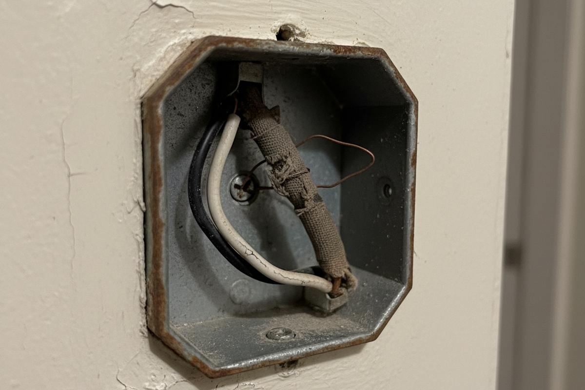
Com o circuito desenergizado, remova ambas as espelhos de parede e puxe os interruptores das respetivas caixas, deixando os fios ligados por enquanto. Certifique-se de que nenhum fio descarnado está a tocar noutro ou em qualquer metal. Agora, volte e ligue o disjuntor. Utilizando um detetor de tensão sem contacto, verifique cuidadosamente os fios em cada interruptor. Numa caixa, um único fio (normalmente preto) estará sob tensão. Essa é a sua caixa do lado da linha, onde o sensor Rayzeek irá ficar. A outra caixa, onde nenhum fio está sob tensão, é a caixa do lado da carga. Assim que a tiver encontrado, desligue novamente a alimentação no disjuntor antes de fazer qualquer outra coisa.
O padrão definitivo de cablagem
Com a alimentação desligada e a caixa do lado da linha identificada, pode reconfigurar a cablagem do circuito. Este padrão reatribui um dos fios condutores como uma ligação de comunicação dedicada.
Procura Soluções de Poupança de Energia Ativadas por Movimento?
Contacte-nos para soluções completas de sensores de movimento PIR, produtos de poupança de energia ativados por movimento, interruptores com sensor de movimento e soluções comerciais de ocupação/vacância.
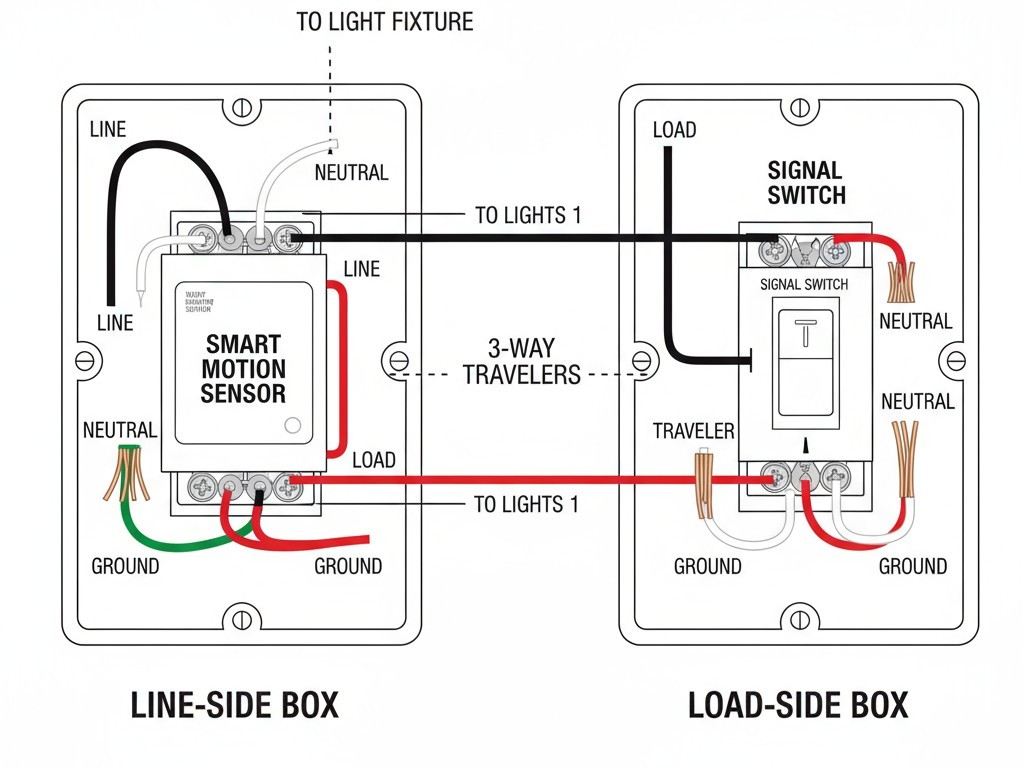
Na caixa do lado da linha (sensor): O sensor Rayzeek vai aqui.
- Ligue o fio preto da “linha” (aquele que identificou como estando sob tensão) ao Linha terminal.
- Bundle the white neutral wires in the box with the sensor’s Neutral wire.
- Connect the ground wires to the sensor’s ground screw. This provides the constant power the sensor needs.
- Choose one traveler wire (often red) to be your signal wire. Connect it to the sensor’s Traveler (or signal) terminal.
- Connect the second traveler wire to the sensor’s Load terminal. This wire will now carry switched power to the light.
In the Load-Side Box (Switch): A standard 3-way switch goes here, but its job is simpler.
- Find the traveler wire coming from the sensor’s Load terminal. Connect this directly to the wire running to the light fixture, bypassing the switch entirely.
- Find the other traveler (your signal wire). Connect it to the common (dark-colored) screw on the 3-way switch.
- Connect the remaining traveler terminal on the switch back to a hot source to complete the signaling circuit, following your sensor’s specific diagram. This switch no longer controls the light directly; it only sends a signal to the sensor.
Stop the Strobe: Set a Longer Timeout
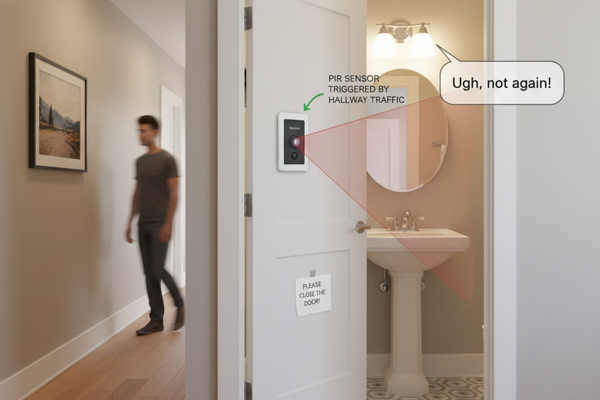
With the wiring done, the final tweak is in the sensor’s settings. The “stair strobe” is almost always caused by a timeout delay that’s too short. If the delay is set to one minute, the lights can switch off while someone is still on the stairs, only to be instantly re-triggered, causing that jarring flash.
Poderá Também Estar Interessado Em

- Tensão: 2 pilhas AAA
- Modo Dia/Noite
- Temporização: 15min, 30min, 1h(padrão), 2h
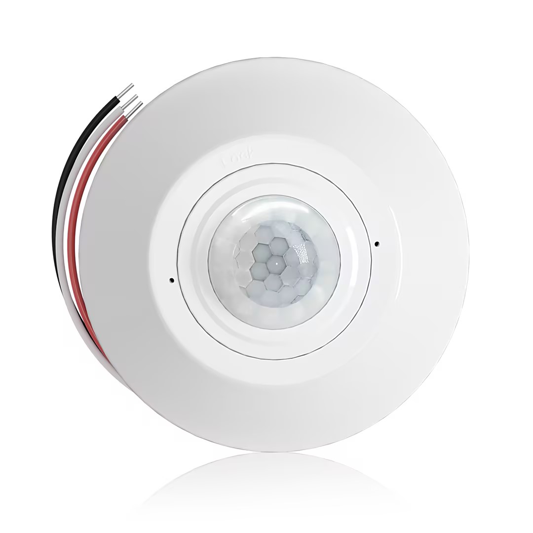
- Sensor de presença PIR para montagem no teto com saída de relé de contacto seco
- Alimentação de baixa tensão de 12/24VDC ou 12/24VAC
- Contactos de relé isolados COM, NO e NC para entradas de controlo de edifícios, HVAC e EMS
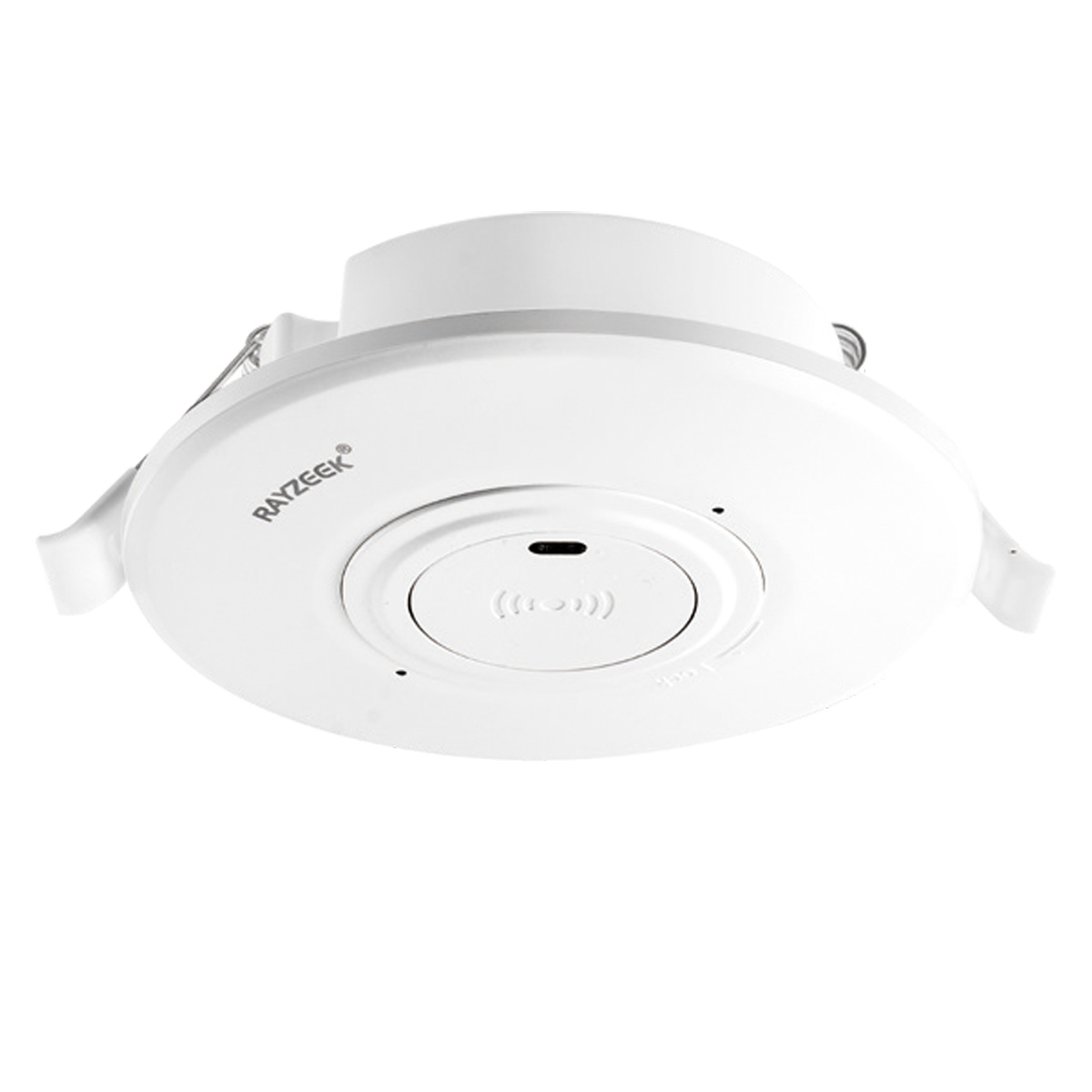
- Interruptor com sensor de movimento por micro-ondas encastrável no teto de baixa tensão DC
- Entrada de 12 VDC / 24 VDC com intervalo de 10-30 VDC
- Corrente máxima de trabalho de 10A com temporizador, limiar Lux e sensibilidade ajustáveis
- Interruptor com sensor de movimento de micro-ondas encastrável no teto para cargas mais elevadas
- Entrada de tensão de linha de 100-265 VAC, modelo de 10A
- Deteção por micro-ondas a 5,8 GHz com temporizador, limiar Lux e sensibilidade ajustáveis
- Interruptor com sensor de movimento de micro-ondas encastrável no teto
- Entrada de tensão de linha de 100-265 VAC, modelo de 5A
- Deteção por micro-ondas a 5,8 GHz com temporizador, limiar Lux e sensibilidade ajustáveis
- Dimmer com sensor de presença PIR RZ037 de montagem no teto para alimentação de 220V
- Corrente máxima de funcionamento de 3A com carga nominal de 660W
- O botão LUX controla o sensor de luz ON/OFF e o brilho de regulação definido pelo utilizador
- Dimmer com sensor de presença PIR RZ037 de montagem no teto para alimentação de 110V
- Corrente máxima de funcionamento de 3A com carga nominal de 330W
- O botão LUX controla o sensor de luz ON/OFF e o brilho de regulação definido pelo utilizador
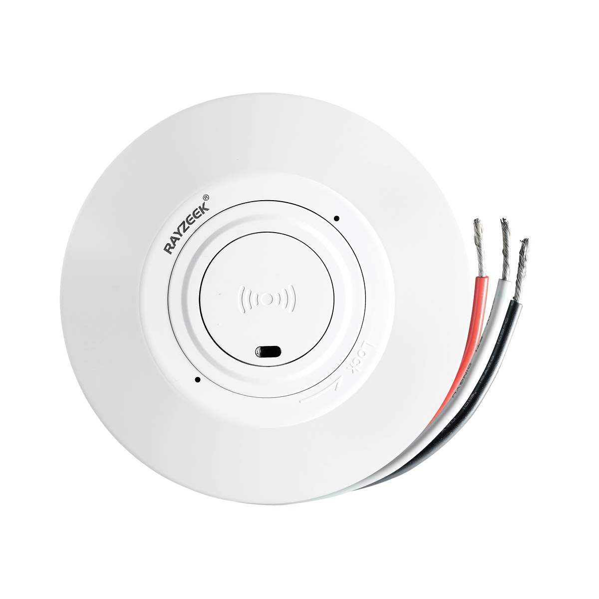
- Interruptor com sensor de movimento por micro-ondas de montagem no teto em DC de baixa tensão
- Entrada de 12 VDC / 24 VDC com intervalo de 10-30 VDC
- Corrente máxima de trabalho de 10A com temporizador, limiar Lux e sensibilidade ajustáveis
- Interruptor de sensor de movimento por micro-ondas para montagem no teto para cargas mais elevadas
- Entrada de tensão de linha de 100-265 VAC, modelo de 10A
- Deteção por micro-ondas a 5,8 GHz com temporizador, limiar Lux e sensibilidade ajustáveis
- Interruptor de sensor de movimento por micro-ondas para montagem no teto
- Entrada de tensão de linha de 100-265 VAC, modelo de 5A
- Deteção por micro-ondas a 5,8 GHz com temporizador, limiar Lux e sensibilidade ajustáveis
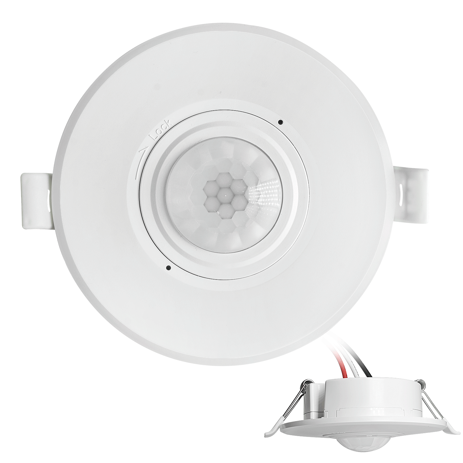
- Interruptor de sensor de movimento PIR para montagem de embutir no teto em CC de baixa tensão
- Entrada de 12 VDC / 24 VDC com intervalo de 10-30 VDC
- Corrente máxima de trabalho de 10A com temporizador, limiar Lux e sensibilidade ajustáveis
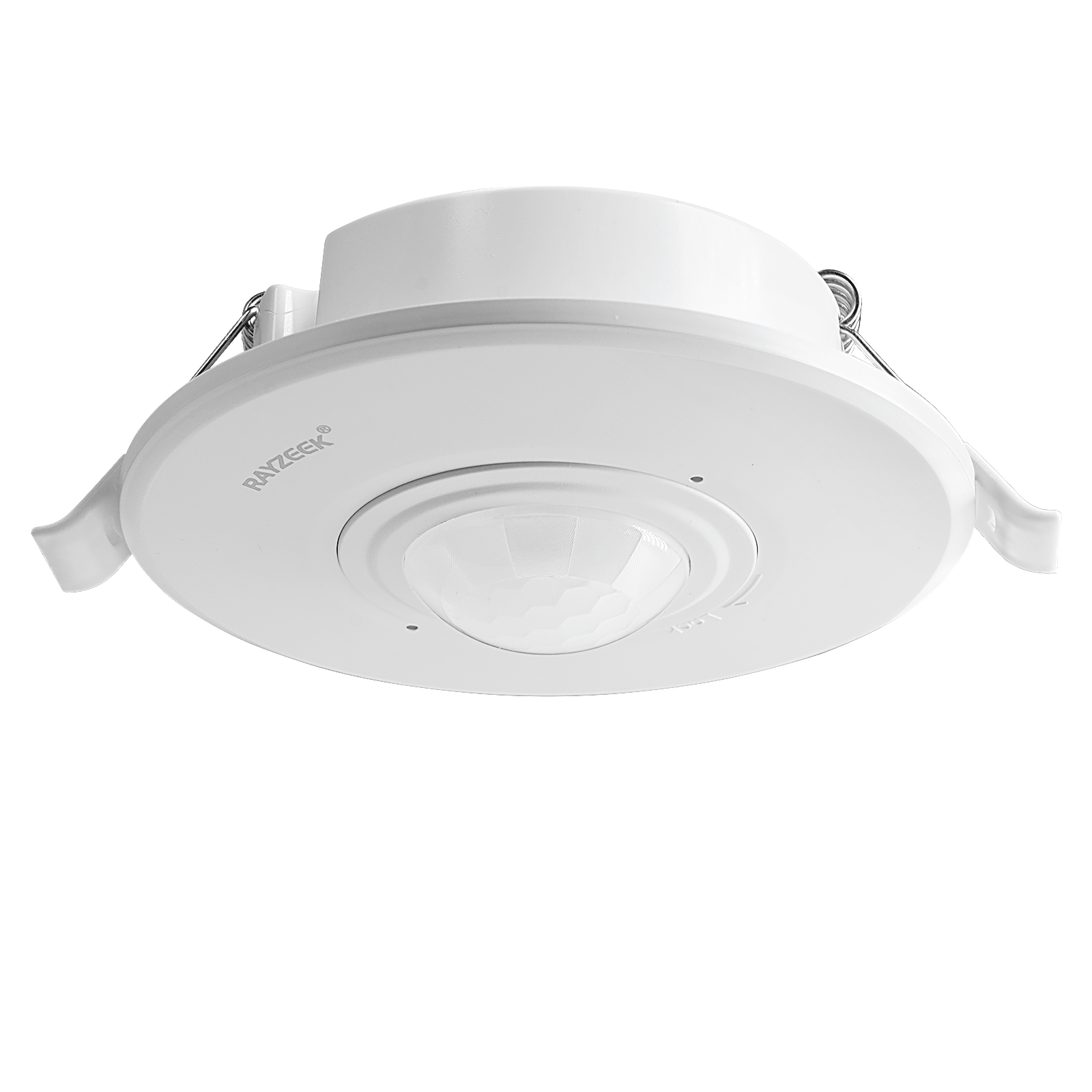
- Interruptor de sensor de movimento PIR para montagem de embutir no teto para cargas mais elevadas
- Entrada de tensão de linha de 100-265 VAC, modelo de 10A
- Deteção de 360 graus com temporizador, limiar Lux e sensibilidade ajustáveis
- Interruptor de sensor de movimento PIR para montagem de embutir no teto
- Entrada de tensão de linha de 100-265 VAC, modelo de 5A
- Deteção de 360 graus com temporizador, limiar Lux e sensibilidade ajustáveis
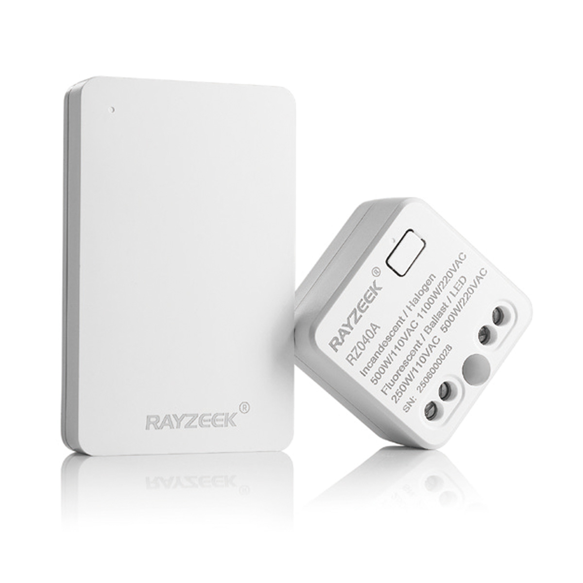
- Kit de interruptor sem fios e recetor para controlo de iluminação interior ON/OFF
- Recetor de 100-230VAC, 50/60Hz com corrente nominal de 5A
- Interruptor sem fios alimentado a pilha CR2032 com comunicação a 2.4GHz
- Ocupação (Ligado automático/Desligado automático)
- 12–24V DC (10–30VDC), até 10A
- Cobertura de 360°, diâmetro de 8–12 m
- Temporização de 15 s–30 min
- Sensor de luz Desligado/15/25/35 Lux
- Sensibilidade Alta/Baixa
- Modo de presença Ligado Automático/Desligado Automático
- 100–265V AC, 10A (neutro necessário)
- Cobertura de 360°; diâmetro de deteção de 8–12 m
- Temporização de 15 s–30 min; Lux Desligado/15/25/35; Sensibilidade Alta/Baixa
- Modo de presença Ligado Automático/Desligado Automático
- 100–265V AC, 5A (neutro necessário)
- Cobertura de 360°; diâmetro de deteção de 8–12 m
- Temporização de 15 s–30 min; Lux Desligado/15/25/35; Sensibilidade Alta/Baixa
For staircases and long hallways, a longer timeout is crucial. Set the Rayzeek sensor’s time delay to at least three to five minutes. This ensures the light stays on for the entire trip between floors, turning a flickering problem area into a smoothly, reliably lit path.
Built to Work
Fixing a 3-way circuit isn’t about finding a clever hack. It’s about implementing a wiring pattern that respects how electricity actually works. By giving the sensor primary control at the line-side box, you create the robust, stable system that defines professional automation. This pattern is designed to do one job perfectly: control a light with absolute reliability, ending the stair strobe for good.