
I den här artikeln undersöker vi om en luftkonditionering räknas som ett termiskt system. Vi går igenom hur en luftkonditionering fungerar på insidan, de termodynamiska principerna bakom dess drift, olika typer av luftkonditioneringssystem samt deras effektivitet. Oavsett om du bara är nyfiken på hur din luftkonditionering fungerar eller är en erfaren forskare har denna ingående analys något för dig.
Vad är egentligen ett termiskt system?
Ett termiskt system hanterar överföring eller omvandling av värmeenergi. Dessa system har sin grund i termodynamikens principer, den gren av fysiken som undersöker sambanden mellan värme, arbete, temperatur och energi. Vardagliga exempel på termiska system inkluderar motorer, kylskåp och värmepumpar. Som vi kommer att se passar luftkonditioneringsapparater väl in i denna kategori.
Termiska system klassificeras övergripande som öppna eller slutna. Öppna system utbyter både materia och energi med sin omgivning. Tänk dig en kastrull med kokande vatten på en spis – den absorberar värme och avger ånga till luften. Slutna system utbyter däremot energi men inte materia. En förseglad tryckkokare fungerar som ett bra exempel på ett slutet system.
Definitionen av en luftkonditionering
En luftkonditionering är en enhet utformad för att kyla och avfukta inomhusluft. Den uppnår detta genom att utvinna värme från inomhusutrymmet och avleda den utomhus. Även om luftkonditionering främst används för komfortkylning i bostäder, kontor och fordon spelar den också en roll vid kylning av industriella processer.
Det inre arbetet: Huvudkomponenterna i en luftkonditionering
Låt oss bryta ned de viktiga delar som gör det möjligt för en luftkonditionering att utföra sitt arbete:
Köldmedium
Detta är arbetsmediet, ett särskilt ämne som cirkulerar mellan vätske- och gasform och absorberar samt avger värme under kylprocessen. Vanliga köldmedier, som R-410A och R-32, har specifika termodynamiska egenskaper, såsom kokpunkt och värmekapacitet, som gör dem väl lämpade för denna uppgift.
Kompressor
Kompressorn betraktas ofta som systemets hjärta, och dess uppgift är att komprimera köldmediet i gasform, vilket avsevärt ökar dess tryck och temperatur. Denna energikrävande process, som vanligtvis drivs av en elmotor, är avgörande för att köldmediet senare ska kunna avge värme i kondensorn. Kompressionsprocessen kan modelleras med hjälp av komplexa ekvationer som den isentropiska kompressionsekvationen, vilken relaterar tryck, volym och kvoten för specifik värme. Dessa ekvationer hjälper oss att fastställa det arbete som kompressorn utför.
Kondensor
Denna komponent fungerar som en värmeväxlare där det varma köldmediet med högt tryck avger sin värme till utomhusmiljön. När det avger värme övergår köldmediet till vätskeform. Kondensorn består vanligtvis av rörslingor och flänsar utformade för att maximera värmeöverföringen. Mängden värme som avges av kondensorn är direkt relaterad till köldmediets massflöde och förändringen i dess entalpi när det kondenserar.
Förångare
Förångaren sitter inomhus och är en annan värmeväxlare. Här absorberar det flytande köldmediet värme från inomhusluften, vilket får det att förångas tillbaka till en gas. Denna värmeabsorption är vad som kyler luften som cirkulerar genom förångarens rörslingor. Samma principer som används för att beräkna värmeöverföring i kondensorn tillämpas här, men förändringen i entalpi motsvarar förångningsprocessen.
Expansionsventil
Denna doseringsenhet reglerar flödet av köldmedium in i förångaren. Den minskar trycket på det flytande köldmediet, vilket gör att det delvis förångas och kyls ned avsevärt. Detta tryckfall är nödvändigt för att köldmediet effektivt ska kunna absorbera värme i förångaren. Expansionsprocessen behandlas vanligtvis som isentalpisk, vilket innebär att köldmediets entalpi förblir konstant före och efter passage genom ventilen.
Hur en luftkonditionering fungerar: Kylcykeln
The refrigeration cycle is a continuous loop involving four key stages: compression, condensation, expansion, and evaporation. Here’s a simplified breakdown:
- The compressor pressurizes and heats the refrigerant gas.
- In the condenser, the hot gas releases heat outdoors and liquefies.
- The expansion valve lowers the refrigerant’s pressure, causing it to cool.
- In the evaporator, the cold refrigerant absorbs indoor heat, cools the air, and reverts to a gas.
This cycle repeats continuously to maintain the desired indoor temperature.
Types of Air Conditioning Systems
Several types of air conditioning systems cater to different needs and preferences:
Split systems have an outdoor unit (housing the compressor and condenser) and an indoor unit (containing the evaporator). They are popular for cooling individual rooms or zones and are known for their quiet operation and flexible installation options.
Window units are self-contained units designed to be installed in a window opening. They are typically used for cooling single rooms and offer a budget-friendly option with relatively easy installation.
Hitta inspiration i Rayzeeks portfölj av rörelsesensorer.
Hittar du inte det du söker? Oroa dig inte. Det finns alltid alternativa sätt att lösa dina problem. Kanske kan någon av våra portföljer hjälpa till.
Central air conditioning systems are designed to cool entire buildings using a network of ducts. They feature a single outdoor unit and a central indoor unit connected to ductwork, providing even cooling distribution and the ability to cool large spaces effectively.
Ductless mini-splits are similar to split systems but eliminate the need for ductwork. They have multiple indoor units connected to a single outdoor unit, offering individual zone control and simplifying installation in existing buildings.
Portable air conditioners are self-contained, movable units. They are often used for temporary or supplemental cooling and offer the advantages of portability and no permanent installation.
Air Conditioners as Thermal Systems: A Clear Connection
So, do air conditioners qualify as thermal systems? Absolutely! They transfer heat from one location (indoors) to another (outdoors) and rely on the principles of thermodynamics, specifically the refrigeration cycle. The refrigeration cycle is a practical application of the fundamental laws of thermodynamics.
Thermodynamic Principles in Air Conditioning: A Deeper Dive
Let’s explore the thermodynamic principles that govern the operation of air conditioners:
The First Law: Energy Conservation
The First Law of Thermodynamics, also known as the law of energy conservation, states that energy cannot be created or destroyed, only transferred or changed in form. In an air conditioner, the electrical energy supplied to the compressor is converted into work performed on the refrigerant. This energy is ultimately transferred as heat to the outdoor environment. The energy balance can be expressed as: Electrical Energy Input equals Heat Rejected to Outdoors minus Heat Absorbed from Indoors.
The Second Law: Entropy and the Flow of Heat
The Second Law of Thermodynamics dictates that the entropy of an isolated system always increases over time. In simpler terms, heat cannot spontaneously flow from a colder body to a hotter one. Air conditioners use work (provided by the compressor) to move heat from a colder space (indoors) to a hotter space (outdoors), a process that aligns with the Second Law. The refrigeration cycle is carefully designed to minimize entropy generation, thereby maximizing efficiency.
Entropy: A Measure of Disorder
Entropy is a measure of disorder or randomness within a system. The Second Law states that the total entropy of a system and its surroundings must always increase for any real process. In an air conditioner, the refrigerant’s entropy decreases as it releases heat in the condenser. However, the entropy of the surroundings increases by a larger amount, resulting in a net increase in overall entropy.
Analyzing the Compressor’s Performance
A compressor’s performance is often analyzed using its isentropic efficiency, which compares the actual work input to the ideal (isentropic) work input for the same pressure ratio. Well-designed compressors typically have isentropic efficiencies between 70-85%. The actual work input can be determined by dividing the isentropic work by the isentropic efficiency. Compressor performance curves, provided by manufacturers, illustrate the relationship between pressure ratio, mass flow rate, and power consumption.
Analyzing the Condenser’s Heat Transfer
The condenser’s heat transfer effectiveness can be analyzed using the Number of Transfer Units (NTU) method. NTU is a dimensionless parameter that represents the heat transfer size of the heat exchanger. The effectiveness of the condenser can be calculated using equations specific to the heat exchanger’s geometry. For instance, a simple counterflow heat exchanger’s effectiveness can be approximated as 1 minus the exponential of negative NTU. Higher effectiveness translates to better heat transfer and improved system efficiency.
Analyzing the Evaporator’s Performance
Similar to the condenser, the evaporator’s performance can also be analyzed using the NTU method. Factors like airflow rate, refrigerant flow rate, and heat exchanger design influence the evaporator’s effectiveness. Optimizing evaporator design can enhance heat transfer and reduce the temperature difference between the refrigerant and the indoor air, leading to better overall system performance.
Analyzing the Expansion Valve’s Role
The expansion valve’s performance is characterized by its ability to maintain a constant superheat at the evaporator outlet. Superheat is the difference between the refrigerant’s actual temperature and its saturation temperature at the evaporator pressure. Proper superheat control ensures that the evaporator is fully utilized and that no liquid refrigerant enters the compressor, which could cause damage. Thermostatic expansion valves (TXVs) use a feedback mechanism to adjust refrigerant flow and maintain a constant superheat.
Heat Transfer in Air Conditioners: A Closer Look
Heat transfer is a fundamental aspect of air conditioning. Let’s examine the three modes of heat transfer involved:
Letar du efter rörelsestyrda energisparande lösningar?
Kontakta oss för kompletta PIR-rörelsesensorer, rörelseaktiverade energisparprodukter, rörelsesensorbrytare och kommersiella lösningar för närvaro/frånvaro (Occupancy/Vacancy).
Conduction: Heat Transfer Through Direct Contact
Conduction is the transfer of heat through direct contact between molecules. In air conditioners, conduction occurs within the refrigerant, the metal walls of the tubing, and the fins of the heat exchangers. The rate of heat conduction is governed by Fourier’s Law, which relates the heat transfer rate to the material’s thermal conductivity, the cross-sectional area, and the temperature gradient.
Convection: Heat Transfer Through Fluid Motion
Convection is the transfer of heat through the movement of fluids (liquids or gases). In air conditioners, convection occurs between the refrigerant and the inner walls of the tubing, and between the air and the outer surfaces of the heat exchangers. Forced convection, driven by fans or pumps, significantly enhances heat transfer rates. Newton’s Law of Cooling describes the rate of heat convection, relating it to the convective heat transfer coefficient, the surface area, and the temperature difference between the surface and the fluid.
Radiation: Heat Transfer Through Electromagnetic Waves
Radiation is the transfer of heat through electromagnetic waves. While less prominent than conduction and convection in typical air conditioning operation, radiation can still play a role, particularly in the condenser. The condenser can radiate heat to the surrounding environment, especially if exposed to direct sunlight. The Stefan-Boltzmann Law governs the rate of heat radiation, relating it to the surface’s emissivity, the Stefan-Boltzmann constant, the surface area, and the absolute temperatures of the radiating surface and the surroundings.
Air Conditioner Efficiency and Performance Metrics: Understanding the Ratings
Several metrics are used to evaluate the efficiency and performance of air conditioners:
SEER (Seasonal Energy Efficiency Ratio)
SEER measures an air conditioner’s cooling output over a typical cooling season, divided by the total electric energy input during the same period. Higher SEER ratings signify greater energy efficiency. SEER is determined through standardized testing procedures that simulate a range of operating conditions.
EER (Energy Efficiency Ratio)
EER measures an air conditioner’s cooling output at a specific operating condition (95°F outdoor temperature, 80°F indoor temperature, and 50% relative humidity), divided by the electric power input at that condition. Higher EER ratings indicate better efficiency at that specific condition.
Coefficient of Performance (COP)
COP measures the efficiency of a heat pump or refrigeration system. It is the ratio of the desired output (heating or cooling) to the required work input. For cooling, COP is the Cooling Output divided by the Work Input. For heating, COP is the Heating Output divided by the Work Input. Higher COP values indicate greater efficiency.
Energy Efficiency Ratio (EER) – A Specific Type of COP
EER is a specific type of COP that applies to cooling systems. It is calculated as the cooling output (in Btu/h) divided by the power input (in watts) at a specific operating condition.
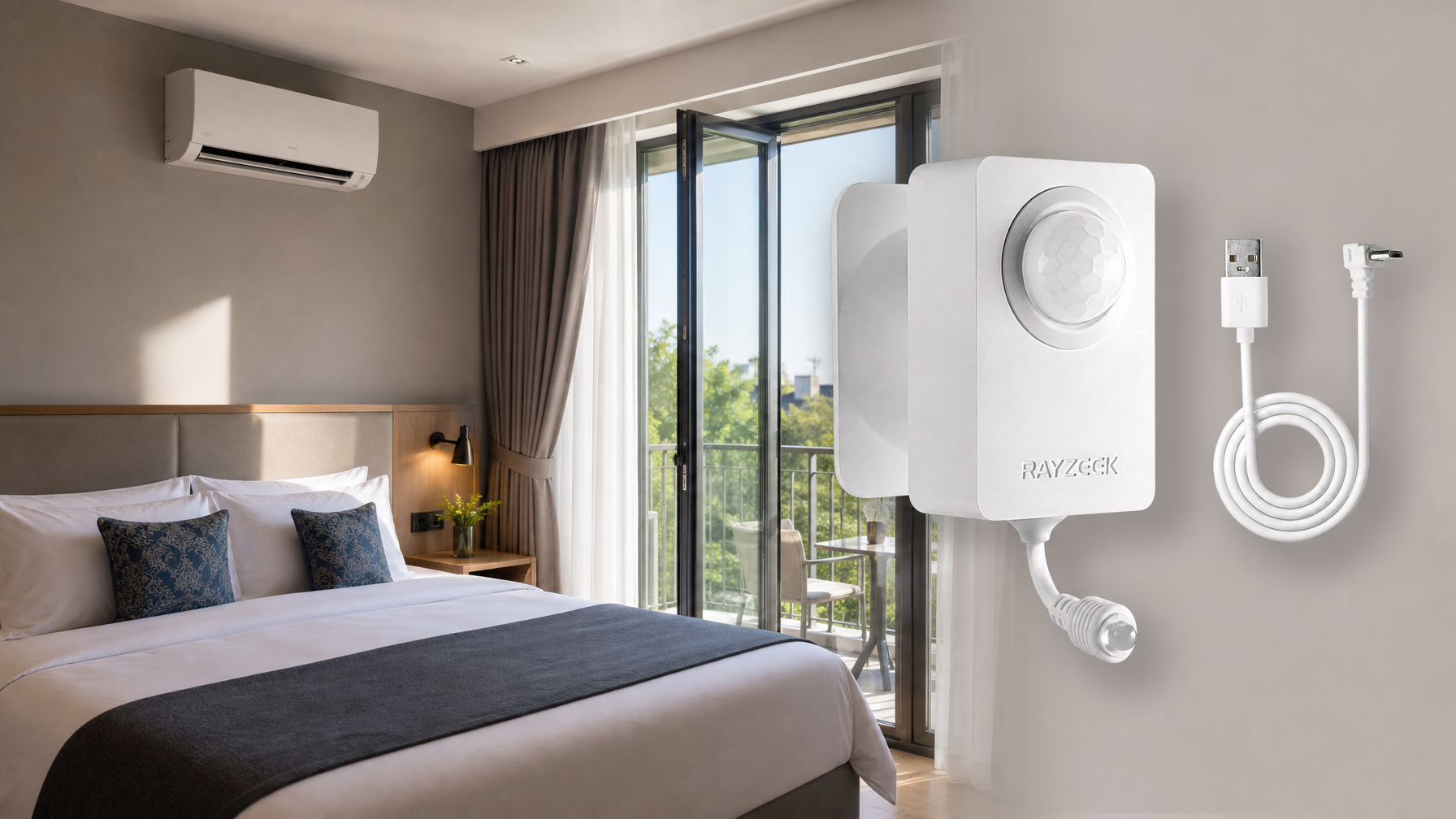
While SEER and EER ratings provide valuable insights into an air conditioner’s efficiency, real-world energy consumption often depends on usage patterns. For instance, leaving the AC running in an empty room drastically reduces its effective efficiency. The Rayzeek RZ050 Air Conditioner Motion Sensor addresses this issue directly by automating the AC’s operation based on occupancy.

Rayzeek RZ050: Maximize Your AC’s Efficiency
Intelligently automates your AC to boost its effective SEER and EER ratings.
- Reduces energy bills by up to 50% by turning off the AC in unoccupied rooms.
- Night mode ensures uninterrupted sleep while still saving energy during the day.
- Helps you achieve optimal energy efficiency beyond the standard ratings.
Is an Air Conditioner a Closed or Open Thermal System?
An air conditioner can be considered a closed thermal system concerning the refrigerant. The refrigerant remains contained within a sealed loop, never mixing with the external environment. However, the air conditioner itself is part of a larger open system, as it exchanges energy (heat) with both the indoor and outdoor environments. It takes in electrical energy and interacts with the air in the room, which is not a closed system.
Advanced Concepts in Air Conditioning Thermodynamics
Let’s explore some more advanced concepts:
Psychrometrics: Understanding Moist Air
Psychrometrics is the study of the thermodynamic properties of moist air. It’s crucial for understanding and designing air conditioning systems. Key psychrometric properties include dry-bulb temperature, wet-bulb temperature, relative humidity, humidity ratio, and enthalpy. Psychrometric charts are graphical tools used to visualize and analyze these properties. Air conditioners not only cool the air but also affect its humidity, making psychrometrics essential for proper system design and operation.
Enthalpy: The Total Heat Content
Enthalpy is a thermodynamic property that represents the total heat content of a system. In air conditioning, enthalpy quantifies the heat content of the refrigerant and the moist air. The change in the refrigerant’s enthalpy during evaporation and condensation determines the system’s cooling capacity. The enthalpy of moist air depends on its temperature and humidity ratio. Enthalpy calculations are essential for determining the cooling load and sizing air conditioning equipment.
Real-World Air Conditioner System Design and Optimization: Beyond the Basics
Designing an efficient air conditioning system involves considering various factors, including:
Du kanske också är intresserad av
- Spänning: 2 AAA-batterier
- Dag-/nattläge
- Tidsfördröjning: 15 min, 30 min, 1 tim (standard), 2 tim
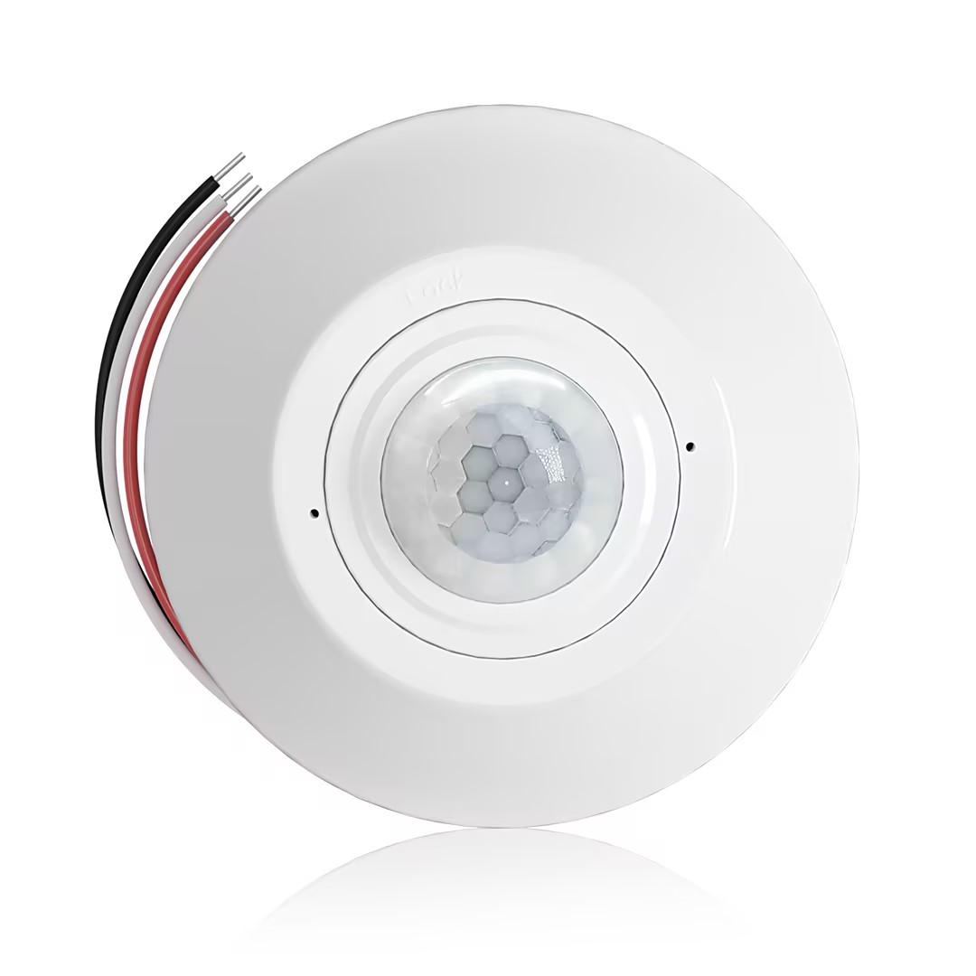
- Takmonterad PIR-närvarosensor med reläutgång för potentialfri kontakt
- 12/24VDC eller 12/24VAC lågspänningsförsörjning
- Isolerade reläkontakter (COM, NO och NC) för styringångar till EMS, VVS och fastighetsautomation
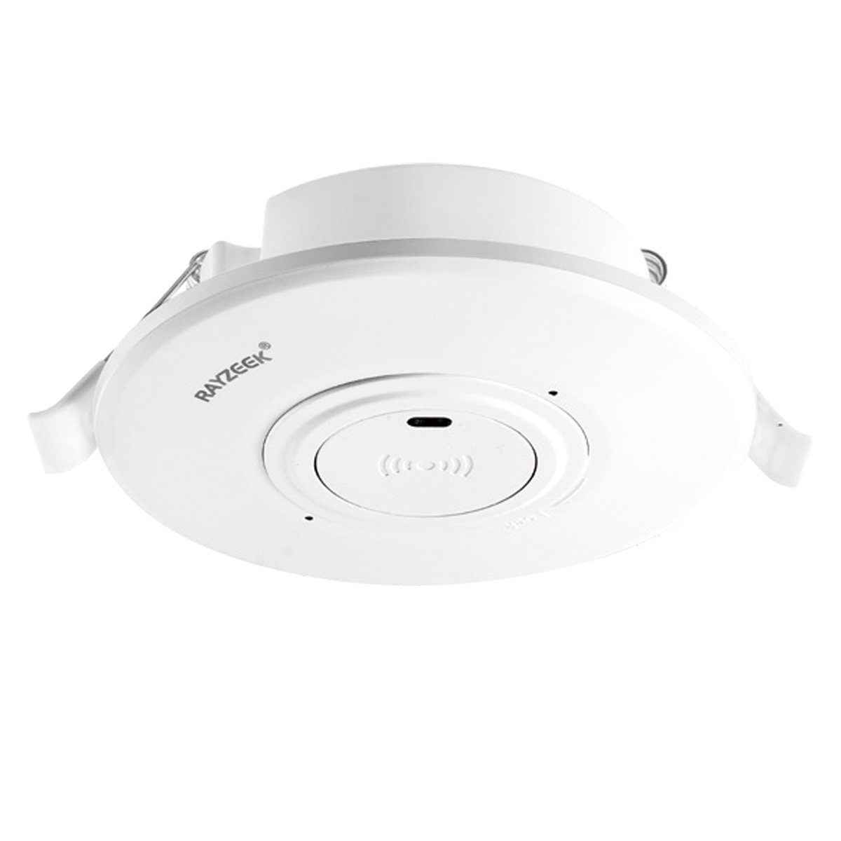
- Lågspänningsdriven (DC) infälld mikrovågsrörelsevakt för tak montering
- 12 VDC / 24 VDC-ingång med ett driftsområde på 10–30 VDC
- Maximal arbetsström på 10A med inställbar tidsfördröjning, Lux-tröskelvärde och känslighet
- Infälld mikrovågsrörelsevakt för tak avsedd för högre belastning
- 100–265 VAC nätspänningsingång, 10A-modell
- 5,8 GHz mikrovågsdetektering med inställbar tidsfördröjning, Lux-tröskelvärde och känslighet
- Infälld takmonterad mikrovågsrörelsesensorbrytare
- 100–265 VAC nätspänningsingång, 5A-modell
- 5,8 GHz mikrovågsdetektering med inställbar tidsfördröjning, Lux-tröskelvärde och känslighet
- Takmonterad RZ037 PIR-närvarosensordimmer för 220V-ström
- 3A maximal arbetsström med 660W märkeffekt
- LUX-knapp styr ljussensor PÅ/AV och användarinställd dimringsnivå
- Takmonterad RZ037 PIR-närvarosensordimmer för 110V-ström
- 3A maximal arbetsström med 330W märkeffekt
- LUX-knapp styr ljussensor PÅ/AV och användarinställd dimringsnivå
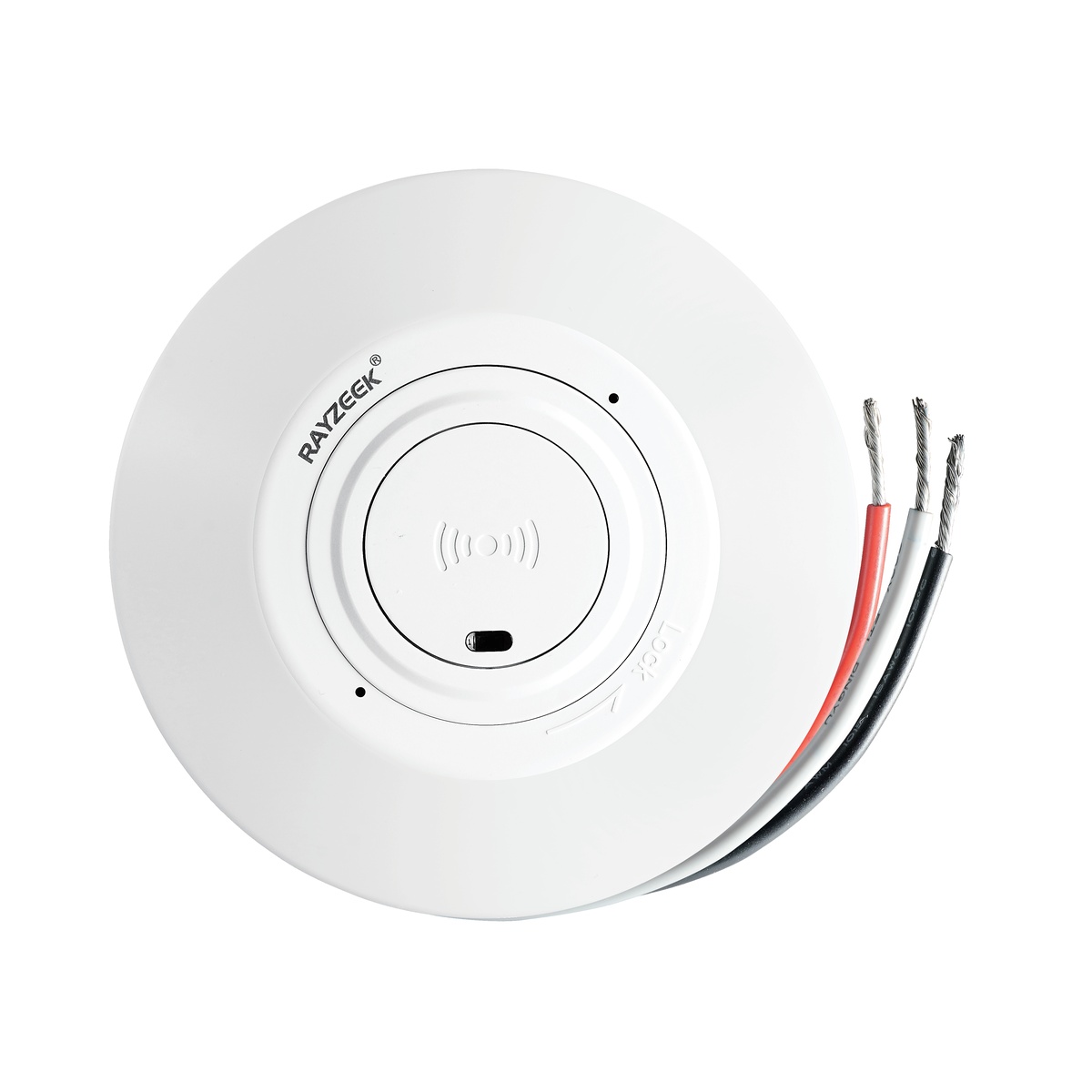
- Lågspännings-DC takmonterad mikrovågsrörelsesensorbrytare
- 12 VDC / 24 VDC-ingång med ett driftsområde på 10–30 VDC
- Maximal arbetsström på 10A med inställbar tidsfördröjning, Lux-tröskelvärde och känslighet
- Takmonterad mikrovågsrörelsesensorbrytare för högre belastning
- 100–265 VAC nätspänningsingång, 10A-modell
- 5,8 GHz mikrovågsdetektering med inställbar tidsfördröjning, Lux-tröskelvärde och känslighet
- Takmonterad mikrovågsrörelsesensorbrytare
- 100–265 VAC nätspänningsingång, 5A-modell
- 5,8 GHz mikrovågsdetektering med inställbar tidsfördröjning, Lux-tröskelvärde och känslighet
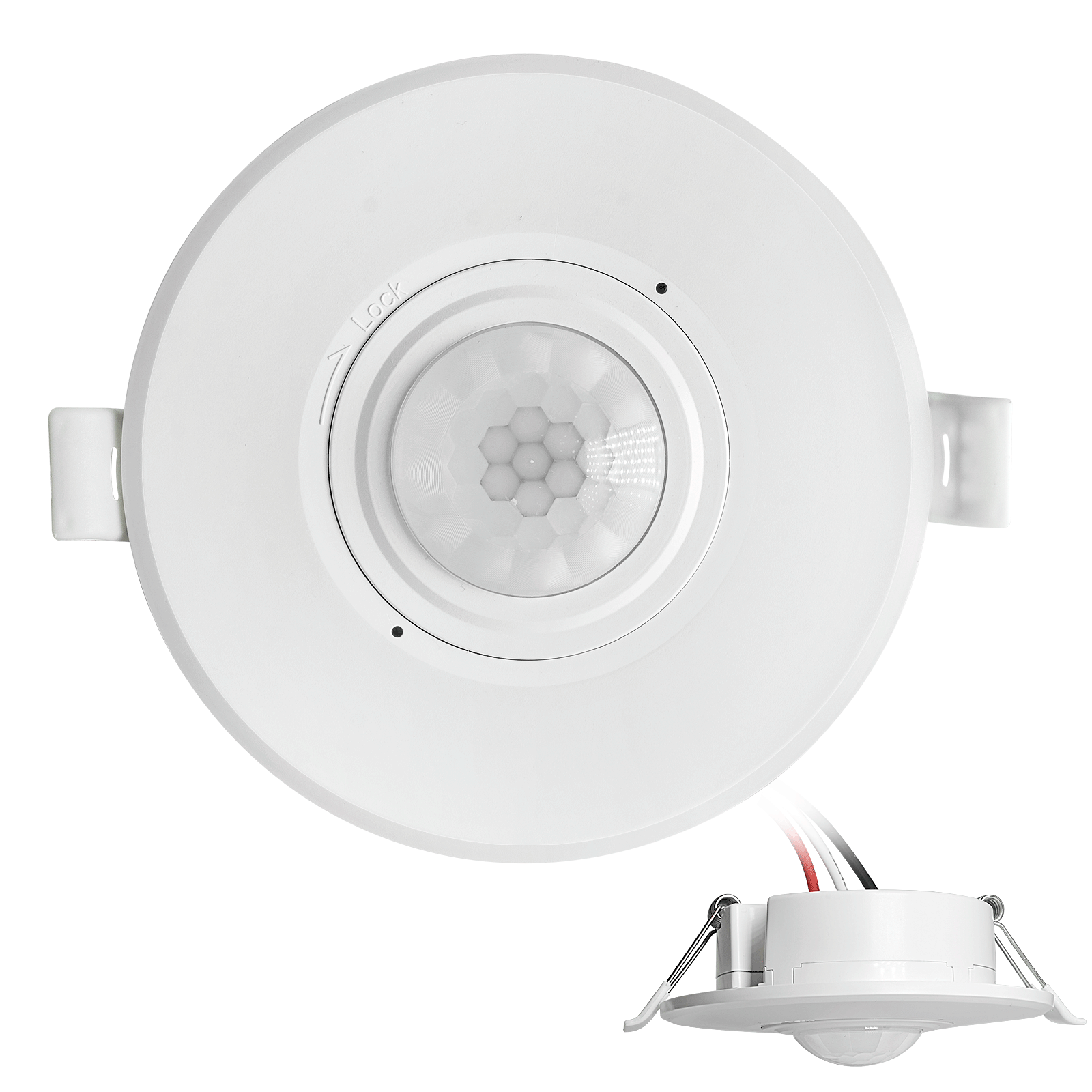
- Lågspännings-DC infälld takmonterad PIR-rörelsesensorströmbrytare
- 12 VDC / 24 VDC-ingång med ett driftsområde på 10–30 VDC
- Max arbetsström 10A med inställbar tidsfördröjning, Lux-tröskelvärde och känslighet
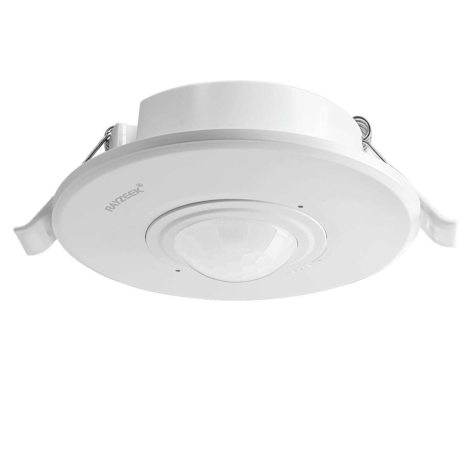
- Infälld takmonterad PIR-rörelsesensorströmbrytare för högre belastning
- 100–265 VAC nätspänningsingång, 10A-modell
- 360-graders detektering med inställbar tidsfördröjning, Lux-tröskelvärde och känslighet
- Infälld takmonterad PIR-rörelsesensorströmbrytare
- 100–265 VAC nätspänningsingång, 5A-modell
- 360-graders detektering med inställbar tidsfördröjning, Lux-tröskelvärde och känslighet
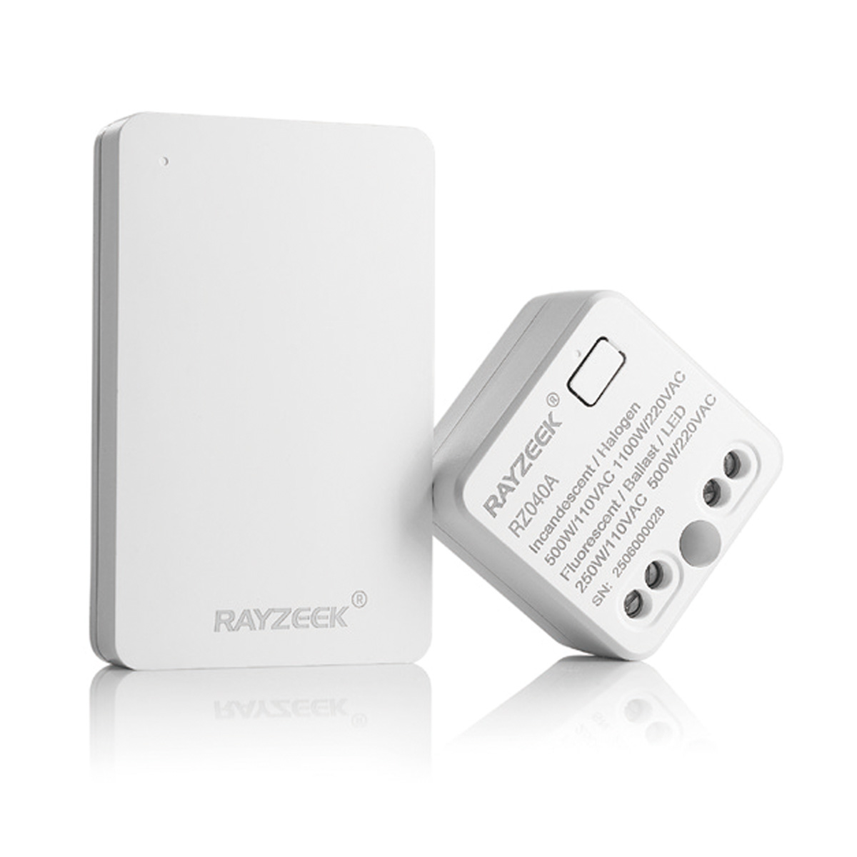
- Trådlöst strömbrytar- och mottagarkit för inomhus belysningsstyrning ON/OFF
- 100-230VAC, 50/60Hz-mottagare med 5A märkström
- CR2032-driven trådlös strömbrytare med 2,4GHz-kommunikation
- Närvaro (Auto-ON/Auto-OFF)
- 12–24V DC (10–30VDC), upp till 10A
- 360° täckning, 8–12 m diameter
- Tidsfördröjning 15 s–30 min
- Ljussensor Off/15/25/35 Lux
- Hög/Låg känslighet
- Automatisk På/Automatisk Av närvaroläge
- 100–265V AC, 10A (nolla krävs)
- 360° täckning; 8–12 m detekteringsdiameter
- Tidsfördröjning 15 s–30 min; Lux AV/15/25/35; Känslighet Hög/Låg
- Automatisk På/Automatisk Av närvaroläge
- 100–265V AC, 5A (nolla krävs)
- 360° täckning; 8–12 m detekteringsdiameter
- Tidsfördröjning 15 s–30 min; Lux AV/15/25/35; Känslighet Hög/Låg
- Climate: Understanding the outdoor temperature and humidity variations throughout the year is crucial for selecting the right system.
- Building Load: Accurately estimating the amount of heat that needs to be removed from the building is essential. This depends on factors like insulation, occupancy, and internal heat gains.
- Control Strategies: Employing advanced control systems, such as variable refrigerant flow (VRF) or variable-speed compressors, can optimize performance under varying loads.
Optimization Techniques for Maximum Efficiency
Optimization techniques can be used to minimize energy consumption while maintaining desired comfort levels. This may involve using simulation software to model system performance under different operating conditions. Life-cycle cost analysis can help evaluate the long-term economic and environmental impact of different design choices.
Thermodynamic Limitations: The Boundaries of Efficiency
- The Carnot cycle represents the theoretical upper limit of efficiency for any heat engine or refrigeration cycle operating between two temperatures.
- Real-world air conditioners have efficiencies significantly lower than the Carnot efficiency due to irreversibilities in the compression process, heat transfer limitations, and other factors.
The Future of Air Conditioning: Pushing the Boundaries
Current research is focused on developing new refrigerants with lower global warming potential and exploring alternative cooling technologies that can overcome the limitations of the conventional vapor-compression cycle.
One promising area is the development of more sophisticated control algorithms that can dynamically adjust system operation based on real-time weather data, occupancy patterns, and energy prices. This could lead to significant energy savings and improved comfort.
Another area of interest is the integration of thermal storage technologies with air conditioning systems. This could allow for shifting cooling loads to off-peak hours, reducing electricity costs and grid strain.