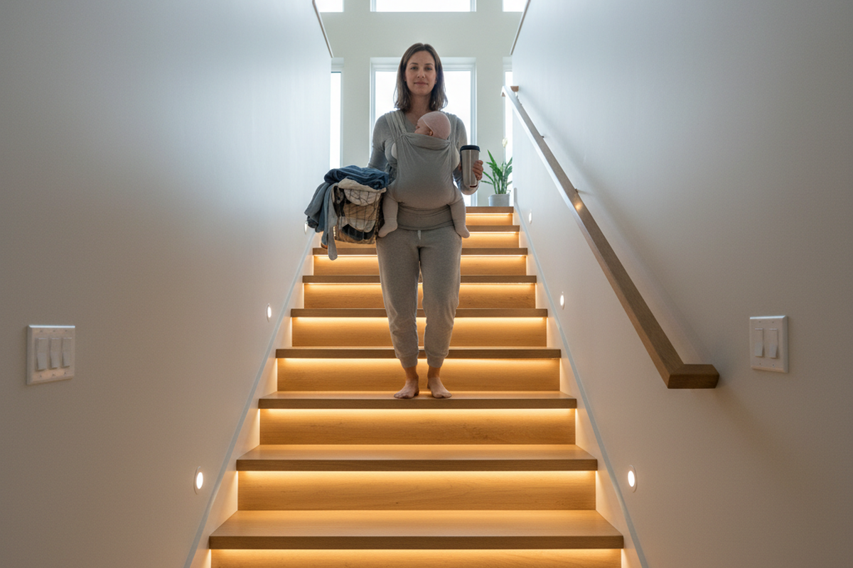
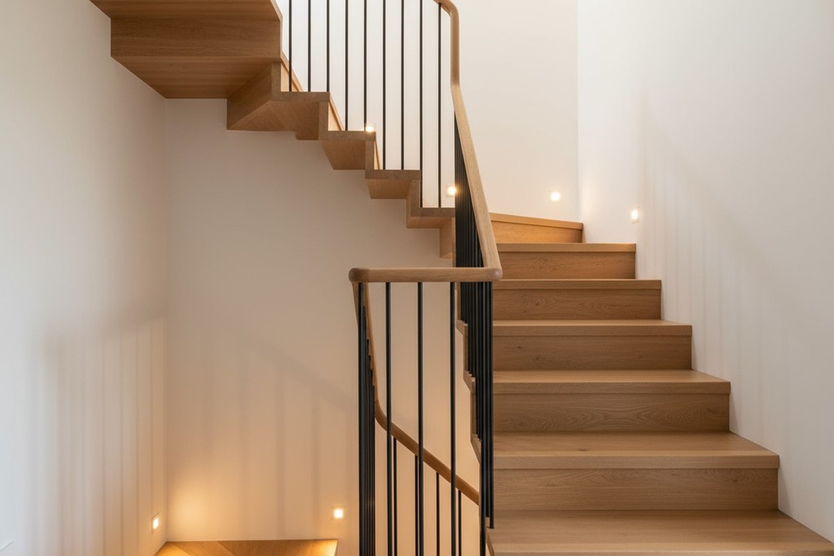
The staircase is a space of constant motion, but automating its lighting often creates an electrical nightmare. Instead of smooth, reliable light, you get the “stair strobe”—a flickering, unpredictable mess where lights flash as someone walks up the stairs or refuse to respond to one of the switches.
This isn’t a faulty motion sensor. It’s a faulty wiring plan. A standard 3-way circuit was designed for simple mechanical switches, and dropping a smart sensor into that old design without a strategy is asking for trouble. A clean, reliable system requires a new approach that establishes a clear hierarchy of control.
The Traveler Wire Conflict: Why Old 3-Way Circuits Fight Automation
A conventional 3-way circuit is a clever design for controlling one light from two spots. It uses two “traveler” wires running between the switches. Think of the switches as track changers for electricity. Flipping either switch breaks one electrical path and completes another, turning the light on or off.
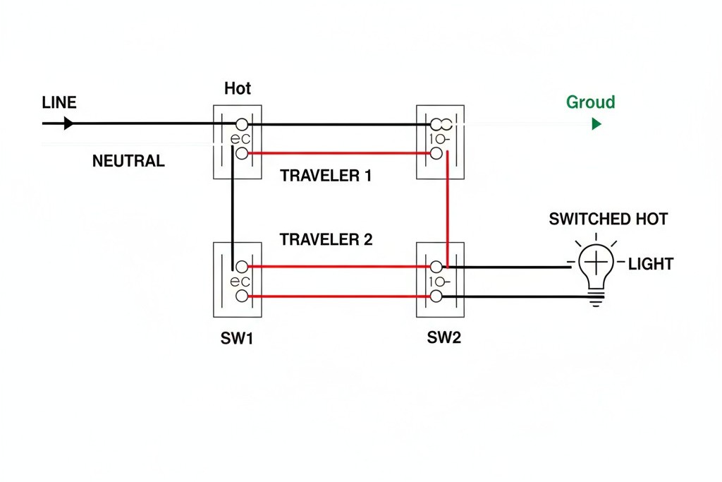
The design is simple, but it has a fatal flaw for automation: at any given moment, only one of the two traveler wires is live. A motion sensor, being an electronic device, needs a constant supply of power for its internal brain. It can’t function if its own power source is being cut by a second switch down the hall. When you install a sensor in a traditional 3-way setup, the sensor and the mechanical switch end up fighting for control, creating the erratic behavior that plagues so many projects.
Вдохновляйтесь линейками датчиков движения Rayzeek.
Не нашли то, что искали? Не волнуйтесь, всегда есть альтернативные варианты решения ваших задач. Возможно, вам подойдет одна из наших линеек продукции.
The Point of Command: Why the Sensor Goes in the Line-Side Box
To build a stable smart circuit, one device must have the final say. The motion sensor needs to be the primary controller, deciding when the circuit gets power. The second switch simply becomes a way to send a “request” to the sensor. For this to work, the sensor must be installed where the power enters the circuit.
In any 3-way setup, one electrical box contains the “line” wire from the breaker panel, and the other contains the “load” wire running to the light fixture. By placing the Rayzeek sensor in the line-side box, you position it to manage all incoming power. It can power itself reliably and then decide whether to send electricity on to the light, based on motion or a signal from the other switch. This architecture transforms a power struggle into an orderly system with a clear chain of command.
Finding the Power Source: The First Step
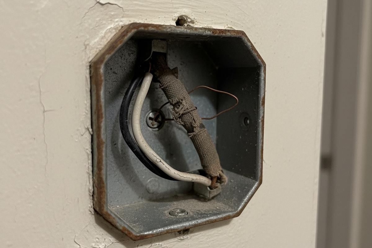
Before you touch a single wire, you have to find the line-side box. First, kill the power to the circuit at the breaker panel.
With the circuit de-energized, remove both wall plates and pull the switches from their boxes, leaving the wires attached for now. Make sure no bare wires are touching each other or any metal. Now, go back and turn the breaker on. Using a non-contact voltage tester, carefully check the wires at each switch. In one box, a single wire (usually black) will be hot. That’s your line-side box, where the Rayzeek sensor will go. The other box, where no wires are live, is the load-side box. Once you’ve found it, turn the power off at the breaker again before you do anything else.
The Definitive Wiring Pattern
With the power off and the line-side box identified, you can rewire the circuit. This pattern repurposes one of the traveler wires as a dedicated communication link.
Ищете энергосберегающие решения с датчиками движения?
Свяжитесь с нами, чтобы заказать готовые PIR-датчики движения, энергосберегающие устройства с активацией по движению, выключатели с датчиками движения, а также коммерческие решения контроля присутствия (Occupancy/Vacancy).
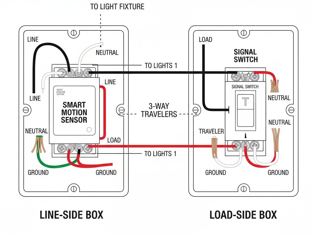
In the Line-Side Box (Sensor): The Rayzeek sensor goes here.
- Connect the black “line” wire (the one you identified as hot) to the sensor’s Line terminal.
- Bundle the white neutral wires in the box with the sensor’s Neutral wire.
- Connect the ground wires to the sensor’s ground screw. This provides the constant power the sensor needs.
- Choose one traveler wire (often red) to be your signal wire. Connect it to the sensor’s Traveler (or signal) terminal.
- Connect the second traveler wire to the sensor’s Load terminal. This wire will now carry switched power to the light.
In the Load-Side Box (Switch): A standard 3-way switch goes here, but its job is simpler.
- Find the traveler wire coming from the sensor’s Load terminal. Connect this directly to the wire running to the light fixture, bypassing the switch entirely.
- Find the other traveler (your signal wire). Connect it to the common (dark-colored) screw on the 3-way switch.
- Connect the remaining traveler terminal on the switch back to a hot source to complete the signaling circuit, following your sensor’s specific diagram. This switch no longer controls the light directly; it only sends a signal to the sensor.
Stop the Strobe: Set a Longer Timeout
With the wiring done, the final tweak is in the sensor’s settings. The “stair strobe” is almost always caused by a timeout delay that’s too short. If the delay is set to one minute, the lights can switch off while someone is still on the stairs, only to be instantly re-triggered, causing that jarring flash.
Возможно, вас заинтересует

- Напряжение: 2 батарейки типа AAA
- Режим День/Ночь
- Задержка времени: 15 мин, 30 мин, 1 ч (по умолчанию), 2 ч
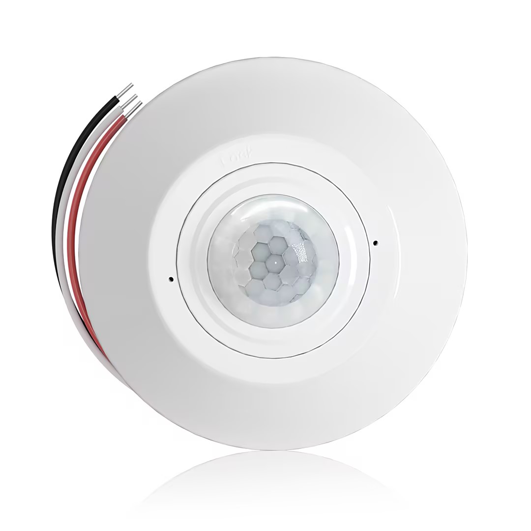
- Потолочный PIR-датчик присутствия с выходом реле с сухими контактами
- Низковольтное питание 12/24VDC или 12/24VAC
- Изолированные контакты реле COM, NO и NC для систем управления зданием (EMS), ОВК (HVAC) и автоматизации
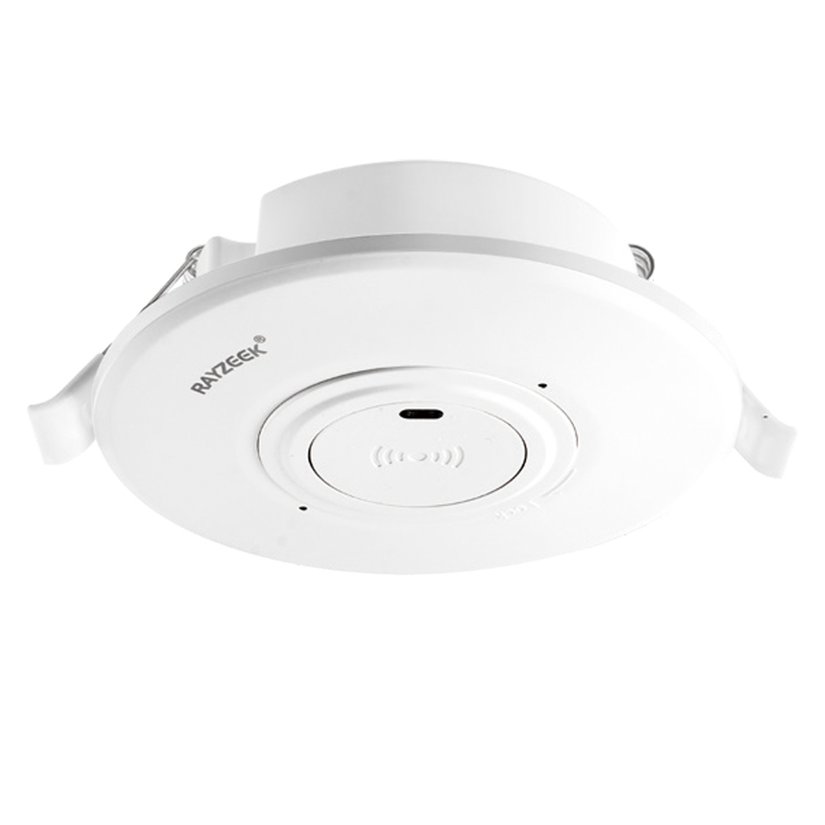
- Низковольтный встраиваемый потолочный микроволновый выключатель с датчиком движения постоянного тока
- Вход 12 VDC / 24 VDC с диапазоном 10-30 VDC
- Максимальный рабочий ток 10A с регулируемой задержкой времени, порогом освещенности (Lux) и чувствительностью
- Встраиваемый в потолок микроволновый датчик движения (выключатель) для повышенной нагрузки
- Входное сетевое напряжение 100-265 VAC, модель на 10A
- Микроволновое обнаружение на частоте 5.8 GHz с регулировкой задержки времени, порога освещенности (Lux) и чувствительности
- Встраиваемый в потолок микроволновый датчик движения (выключатель)
- Входное сетевое напряжение 100-265 VAC, модель на 5A
- Микроволновое обнаружение на частоте 5.8 GHz с регулировкой задержки времени, порога освещенности (Lux) и чувствительности
- Потолочный PIR-датчик присутствия с функцией диммера RZ037 для сетей 220V
- Максимальный рабочий ток 3A с номинальной нагрузкой 660W
- Кнопка LUX управляет включением/выключением датчика освещенности и установленной пользователем яркостью диммирования
- Потолочный PIR-датчик присутствия с функцией диммера RZ037 для сетей 110V
- Максимальный рабочий ток 3A с номинальной нагрузкой 330W
- Кнопка LUX управляет включением/выключением датчика освещенности и установленной пользователем яркостью диммирования
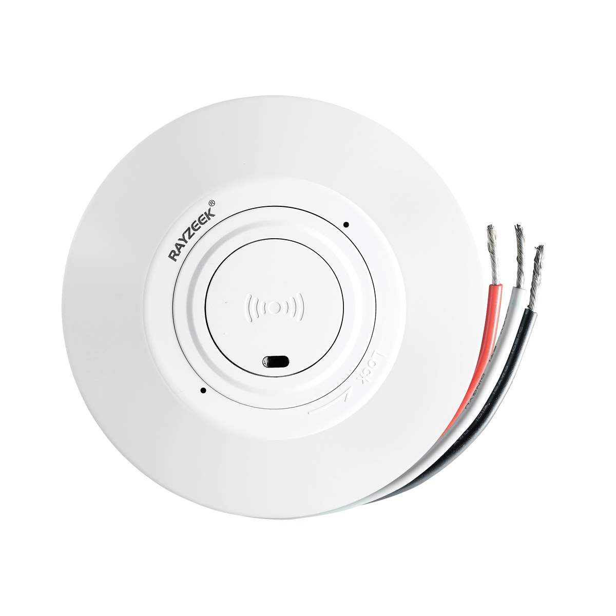
- Низковольтный потолочный микроволновый датчик движения (выключатель) постоянного тока (DC)
- Вход 12 VDC / 24 VDC с диапазоном 10-30 VDC
- Максимальный рабочий ток 10A с регулируемой задержкой времени, порогом освещенности (Lux) и чувствительностью
- Потолочный микроволновый датчик движения (выключатель) для повышенной нагрузки
- Входное сетевое напряжение 100-265 VAC, модель на 10A
- Микроволновое обнаружение на частоте 5.8 GHz с регулировкой задержки времени, порога освещенности (Lux) и чувствительности
- Потолочный микроволновый датчик движения (выключатель)
- Входное сетевое напряжение 100-265 VAC, модель на 5A
- Микроволновое обнаружение на частоте 5.8 GHz с регулировкой задержки времени, порога освещенности (Lux) и чувствительности
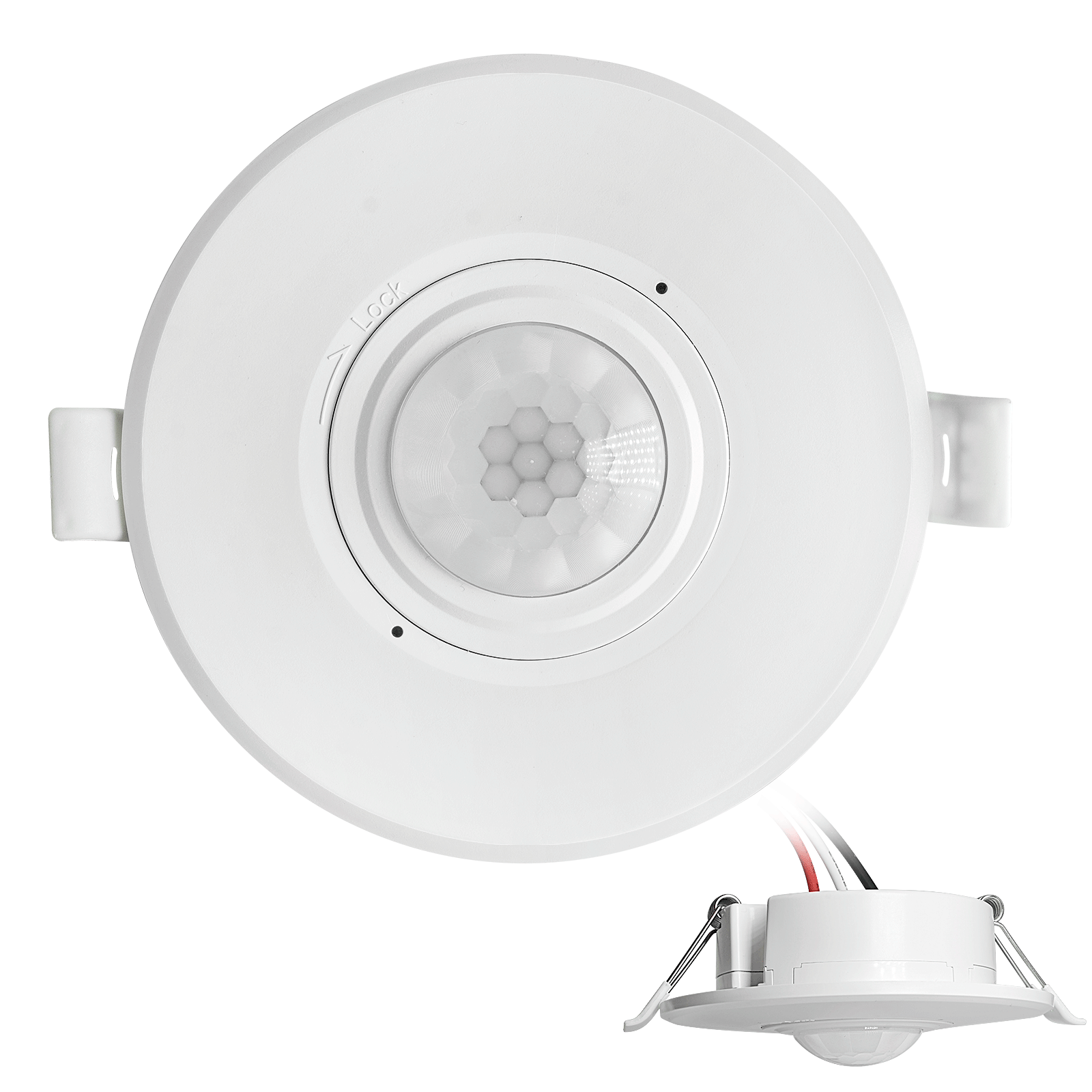
- Низковольтный встраиваемый потолочный датчик-выключатель движения PIR постоянного тока
- Вход 12 VDC / 24 VDC с диапазоном 10-30 VDC
- Максимальный рабочий ток 10 А с регулировкой задержки времени, порога освещенности (Lux) и чувствительности
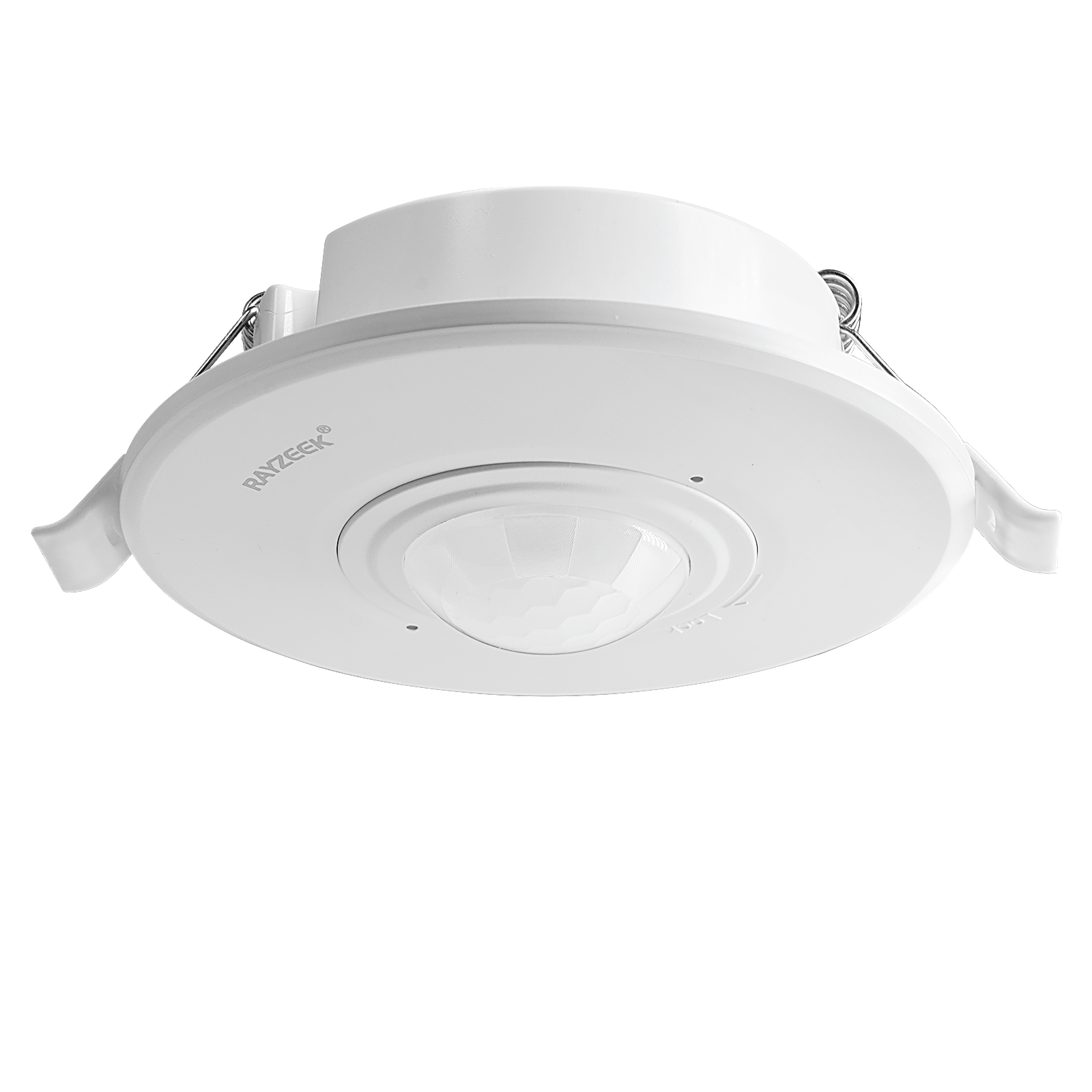
- Встраиваемый потолочный датчик-выключатель движения PIR для повышенной нагрузки
- Входное сетевое напряжение 100-265 VAC, модель на 10A
- Обнаружение на 360 градусов с регулировкой задержки времени, порога освещенности (Lux) и чувствительности
- Встраиваемый потолочный датчик-выключатель движения PIR
- Входное сетевое напряжение 100-265 VAC, модель на 5A
- Обнаружение на 360 градусов с регулировкой задержки времени, порога освещенности (Lux) и чувствительности
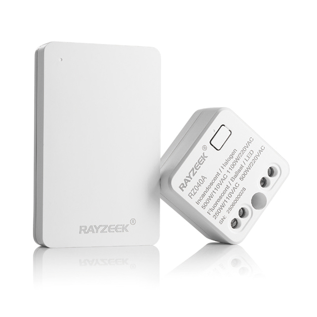
- Комплект из беспроводного выключателя и приемника для управления внутренним освещением (вкл/выкл)
- Приемник 100–230 В переменного тока, 50/60 Гц с номинальным током 5 А
- Беспроводной выключатель на базе батарейки CR2032 с частотой связи 2.4 ГГц
- Контроль присутствия (автоматическое включение и выключение)
- 12–24 В постоянного тока (10–30 В постоянного тока), до 10 А
- Зона покрытия 360°, диаметр обнаружения 8–12 м
- Задержка времени от 15 с до 30 мин
- Датчик освещенности: Выкл / 15 / 25 / 35 Люкс
- Высокая/низкая чувствительность
- Режим присутствия: авто-включение / авто-выключение
- 100–265V AC, 10A (требуется нейтраль)
- Зона покрытия 360°; диаметр обнаружения 8–12 м
- Задержка времени 15 с–30 мин; Lux ВЫКЛ/15/25/35; Чувствительность Высокая/Низкая
- Режим присутствия: авто-включение / авто-выключение
- 100–265V AC, 5A (требуется нейтраль)
- Зона покрытия 360°; диаметр обнаружения 8–12 м
- Задержка времени 15 с–30 мин; Lux ВЫКЛ/15/25/35; Чувствительность Высокая/Низкая
For staircases and long hallways, a longer timeout is crucial. Set the Rayzeek sensor’s time delay to at least three to five minutes. This ensures the light stays on for the entire trip between floors, turning a flickering problem area into a smoothly, reliably lit path.
Built to Work
Fixing a 3-way circuit isn’t about finding a clever hack. It’s about implementing a wiring pattern that respects how electricity actually works. By giving the sensor primary control at the line-side box, you create the robust, stable system that defines professional automation. This pattern is designed to do one job perfectly: control a light with absolute reliability, ending the stair strobe for good.