The Physiological Cost of Light Shock
There is a specific, sickening sound associated with a failed aquarium lighting strategy. It is the wet slap of a $300 Exquisite Fairy Wrasse hitting the carpet at 2:00 AM. The fish isn’t suicidal. It hit the floor because it was subjected to a violence most hobbyists fail to register: the sudden, absolute snap from total darkness to blinding light.
When a maintenance issue arises in the middle of the night—a return pump grinding, a skimmer overflowing—the operator’s first instinct is often to flip on the room’s overhead LED array or blast the tank with a 1,000-lumen tactical flashlight. To a teleost fish resting in a low-metabolic state, this isn’t illumination. It’s a physical blow.
The biological reaction is immediate and chemically measurable. The fish does not simply “wake up.” The sudden influx of photons triggers a massive, instantaneous release of cortisol. In the wild, such a rapid shift in luminosity doesn’t exist; the sun rises gradually. A binary switch from zero to one hundred percent brightness signals a catastrophic predation event or geological upheaval. The flight response overrides all spatial awareness. Fish bolt. They strike the glass, damage their swim bladders, or find the one square inch of gap in a mesh lid to escape the water entirely.
This risk profile dictates that aquarium task lighting—the illumination used for maintenance, inspection, and emergency repair—must be fundamentally decoupled from aesthetic display lighting. Relying on the main lighting rig (Radions, Hydras, or T5 fixtures) for maintenance is a failure of infrastructure design. The primary lights are for the corals and the viewer. The task lights are for the operator. They must be designed to be biologically invisible to the inhabitants while providing sufficient contrast for the human eye to detect a leaking bulkhead or a stalled needle-wheel pump.
The Biology of Invisibility: Why 660nm Matters
The solution to “waking the tank” lies in the specific spectral limitations of the marine eye. Most reef-dwelling fish have evolved photoreceptors tuned specifically to the blue and green parts of the spectrum (400nm to 550nm), which penetrate deepest into the water column. As you move toward the red end of the spectrum, water absorbs the energy rapidly, meaning red light is virtually non-existent below the first few meters of the ocean surface. Most reef fish lack the retinal cones necessary to process long-wavelength light. To them, pure red light is simply darkness.
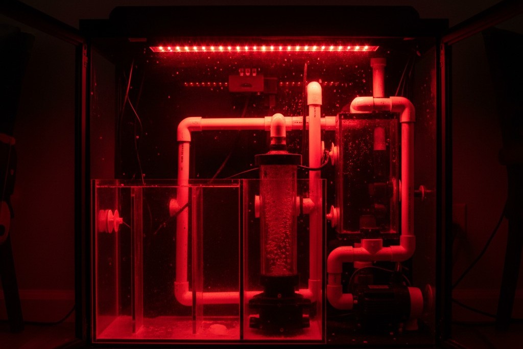
A persistent, dangerous confusion exists in the hobby regarding “Moonlight” modes. Manufacturers of high-end LED fixtures often include a setting that bathes the tank in a dim, deep blue (450nm) glow. While this looks pleasing to the human eye, it is biologically high-energy radiation. It activates photosynthetic processes in zooxanthellae and stimulates the fish’s circadian rhythm. Blue light is a signal to be awake. If the goal is to inspect a sump or display tank without triggering a stress response, blue is the wrong tool. The only safe spectrum is 660nm Red.
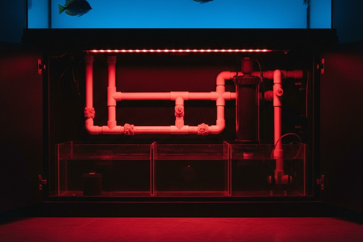
When a 660nm LED strip is engaged, the human operator sees a clear, high-contrast monochrome environment. Pests that are normally skittish (Gorilla Crabs, certain flatworms, mantis shrimp) remain visible and out in the open, unaware they are being observed. The fish remain in their resting torpor. This spectral isolation transforms maintenance from a disruptive event into a stealth operation, allowing for the diagnosis of a rattling impeller or the adjustment of a gate valve without the livestock ever knowing the cabinet has been opened.
Biology rarely deals in absolutes, of course. Specific deep-water species and certain invertebrates possess some sensitivity to the red spectrum. However, for 99% of the livestock kept in mixed reef systems—Tangs, Angels, Wrasses, and Clowns—the 660nm wavelength is effectively an invisibility cloak. The margin of safety provided by red light far outweighs the edge cases where a specific deep-water basslet might detect a faint shimmer.
Inspírese con los portafolios de sensores de movimiento Rayzeek.
¿No encuentra lo que busca? No se preocupe. Siempre existen formas alternativas de resolver sus problemas. Quizá alguno de nuestros portafolios pueda ayudarle.
Engineering for the Salt Spray Zone
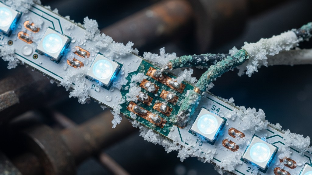
Once the spectrum is selected, the challenge shifts to the hostile environment of the aquarium cabinet. The area inside a sump stand is a corrosion chamber characterized by high humidity, salt aerosol (salt creep), and inevitable water splashing. Standard consumer electronics are not designed for this. A generic LED strip purchased from a big-box store or Amazon, typically rated IP65, is a ticking time bomb. IP65 denotes protection against low-pressure water jets and dust. It does not account for the creeping, crystalline nature of salt, which wicks into connections via capillary action and bridges the gap between positive and negative terminals.
Quizás le interese

- Tensión: 2 pilas AAA
- Modo Día/Noche
- Temporización: 15 min, 30 min, 1 h (por defecto), 2 h
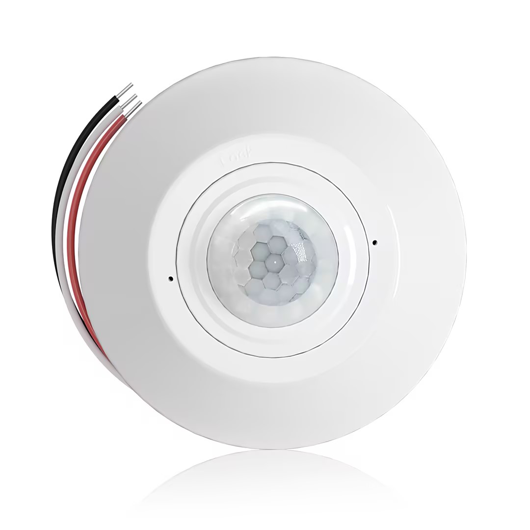
- Sensor de presencia PIR para montaje en techo con salida de relé de contacto seco
- Alimentación de baja tensión de 12/24VDC o 12/24VAC
- Contactos de relé aislados COM, NO y NC para entradas de EMS, HVAC y control de edificios
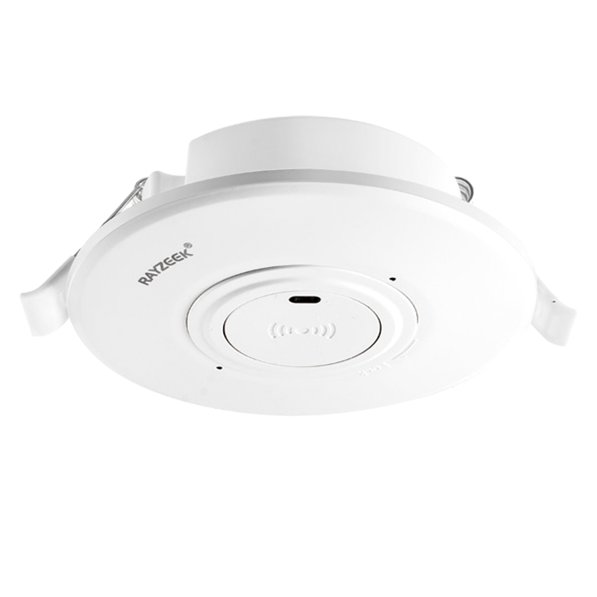
- Interruptor con sensor de movimiento por microondas empotrable en techo de baja tensión DC
- Entrada de 12 VDC / 24 VDC con rango de 10-30 VDC
- Corriente de funcionamiento máxima de 10A con retardo de tiempo, umbral de Lux y sensibilidad ajustables
- Interruptor con sensor de movimiento por microondas empotrable en techo para cargas más elevadas
- Entrada de tensión de red de 100-265 VAC, modelo de 10A
- Detección por microondas de 5,8 GHz con temporizador, umbral Lux y sensibilidad ajustables
- Interruptor con sensor de movimiento por microondas empotrable para techo
- Entrada de tensión de red de 100-265 VAC, modelo de 5A
- Detección por microondas de 5,8 GHz con temporizador, umbral Lux y sensibilidad ajustables
- Regulador con sensor de presencia PIR RZ037 de techo para alimentación de 220V
- Corriente de funcionamiento máxima de 3A con carga nominal de 660W
- El botón LUX controla el encendido/apagado del sensor de luz y la regulación de brillo ajustada por el usuario
- Regulador con sensor de presencia PIR RZ037 de techo para alimentación de 110V
- Corriente de funcionamiento máxima de 3A con carga nominal de 330W
- El botón LUX controla el encendido/apagado del sensor de luz y la regulación de brillo ajustada por el usuario
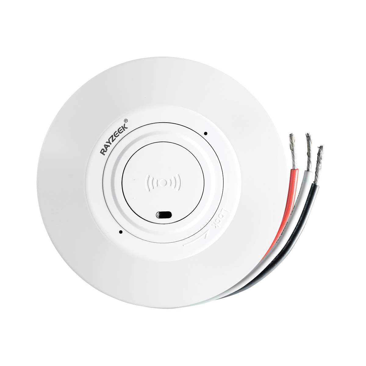
- Interruptor con sensor de movimiento por microondas de techo para CC de bajo voltaje
- Entrada de 12 VDC / 24 VDC con rango de 10-30 VDC
- Corriente de funcionamiento máxima de 10A con retardo de tiempo, umbral de Lux y sensibilidad ajustables
- Interruptor con sensor de movimiento por microondas de techo para mayor carga
- Entrada de tensión de red de 100-265 VAC, modelo de 10A
- Detección por microondas de 5,8 GHz con temporizador, umbral Lux y sensibilidad ajustables
- Interruptor con sensor de movimiento por microondas de techo
- Entrada de tensión de red de 100-265 VAC, modelo de 5A
- Detección por microondas de 5,8 GHz con temporizador, umbral Lux y sensibilidad ajustables
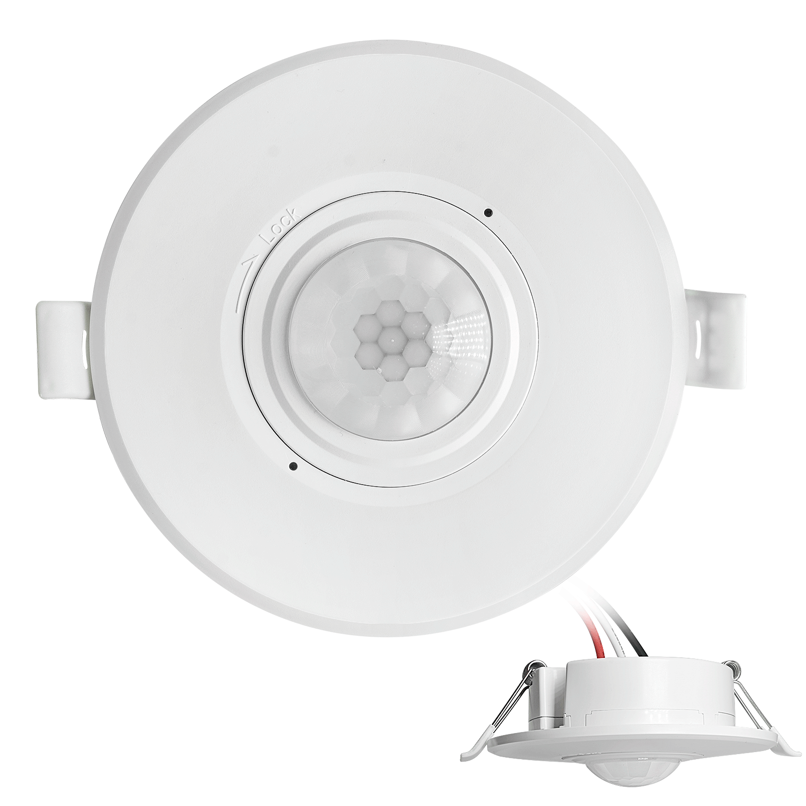
- Interruptor con sensor de movimiento PIR para montaje empotrable en techo de CC de bajo voltaje
- Entrada de 12 VDC / 24 VDC con rango de 10-30 VDC
- Corriente máxima de trabajo de 10 A con tiempo de retardo, umbral de luxes y sensibilidad ajustables
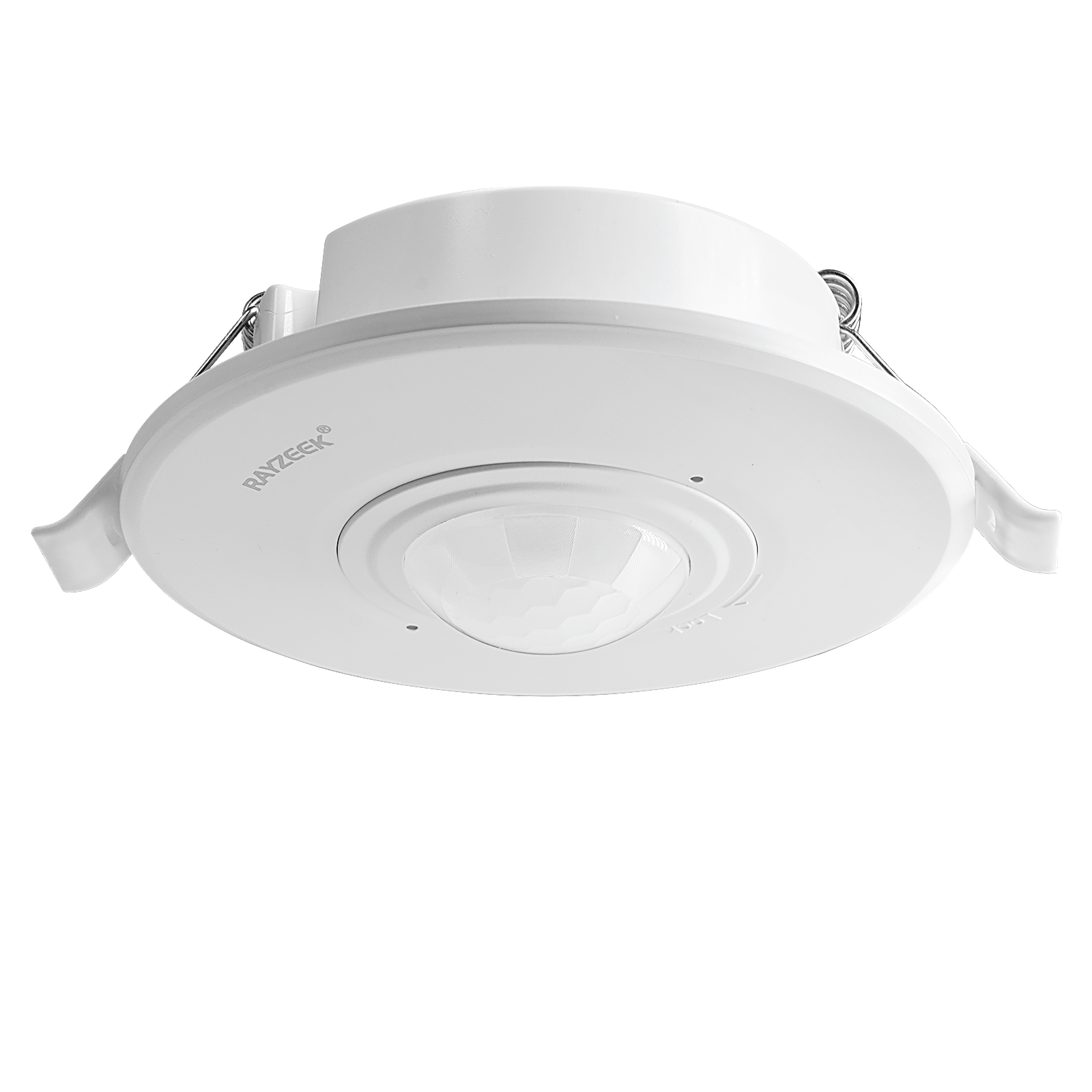
- Interruptor con sensor de movimiento PIR empotrable en techo para mayor carga
- Entrada de tensión de red de 100-265 VAC, modelo de 10A
- Detección de 360 grados con tiempo de retardo, umbral de luxes y sensibilidad ajustables
- Interruptor con sensor de movimiento PIR empotrable en techo
- Entrada de tensión de red de 100-265 VAC, modelo de 5A
- Detección de 360 grados con tiempo de retardo, umbral de luxes y sensibilidad ajustables
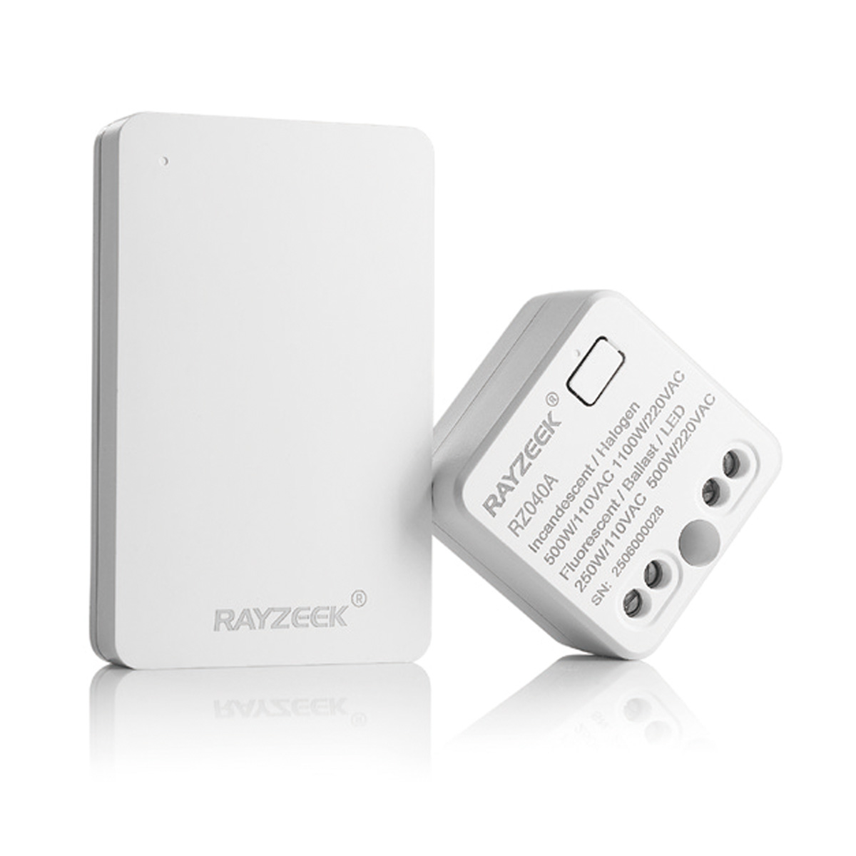
- Kit de emisor inalámbrico y receptor para el control de iluminación de encendido/apagado en interiores
- Receptor de 100-230 V CA, 50/60 Hz con corriente nominal de 5 A
- Interruptor inalámbrico alimentado por CR2032 con comunicación de 2,4 GHz
- Presencia (encendido automático/apagado automático)
- 12–24 V CC (10–30 V CC), hasta 10 A
- Cobertura de 360°, 8–12 m de diámetro
- Tiempo de retardo de 15 s a 30 min
- Sensor de luz Desactivado/15/25/35 Lux
- Sensibilidad alta/baja
- Modo de presencia con encendido/apagado automático
- 100–265V CA, 10A (requiere neutro)
- Cobertura de 360°; diámetro de detección de 8–12 m
- Temporización: 15 s–30 min; Lux OFF/15/25/35; Sensibilidad Alta/Baja
- Modo de presencia con encendido/apagado automático
- 100–265V CA, 5A (requiere neutro)
- Cobertura de 360°; diámetro de detección de 8–12 m
- Temporización: 15 s–30 min; Lux OFF/15/25/35; Sensibilidad Alta/Baja
The failure mode of a cheap light strip is rarely a simple “burn out.” Instead, salt creep enters the junction points where the strip connects to the power supply or where segments are joined. Once the salt bridge forms, electrolysis begins. The copper traces corrode, turning green and brittle. In a worst-case scenario, this corrosion creates a high-resistance short that generates heat, melting the plastic housing. If this occurs near a GFCI outlet, it trips the circuit, killing power to the return pump and heater. If it occurs on a non-GFCI protected power strip, it becomes a fire hazard.
This makes IP67 the minimum specification for any electronics installed below the waterline, with IP68 (submersible) being preferred. IP67 indicates that the unit is potted—encased in epoxy or silicone—preventing any air or moisture from reaching the diodes or the circuit board. The adhesive backing on these strips is almost universally useless in a humid environment; it will peel within weeks, dropping the live electrical strip into the sump water. Proper installation requires silicone mounting brackets or cyanoacrylate (superglue) gel to bond the strip permanently to the stand ceiling.
We must distinguish this from “Refugium” lighting. Many sumps contain a section for growing macroalgae, lit by intense magenta or white grow lights. This is not task lighting. Refugium lights are blindingly bright and often spill light into the skimmer chamber, causing coralline algae to grow inside the pump body and seize the impeller. Task lighting must be directional and shielded, aimed solely at the equipment. Refugium lighting is for photosynthesis. Mixing the two functions usually results in a cabinet that is blinding to work in and a skimmer that requires acid baths every three months.
The Ergonomics of Emergency: Switching Logic
The mechanism used to trigger task lighting is as critical as the light itself. Consider the context: It is 2:00 AM. The return pump has stopped. The floor is wet. The operator is groggy, anxious, and likely has salt water on their hands. This is not the time to unlock a smartphone, open an app, wait for Wi-Fi to reconnect, and toggle a virtual switch. Nor is it the time to fumble for a tiny inline rocker switch on a power cord buried behind a dosing container.
Relying on “Smart Home” sensors—Zigbee motion detectors or Wi-Fi connected plugs—introduces fragility that has no place in life-support systems. These devices introduce latency. You open the cabinet door, and there is a two-second delay before the cloud server processes the “motion” event. In an emergency, two seconds is an eternity. Furthermore, motion sensors are notorious for timing out while the operator is remaining still, perhaps observing a water level or tightening a union, plunging the workspace back into darkness at a critical moment.
The only robust solution is the mechanical door switch, specifically a magnetic reed switch wired in a Normally Closed (NC) configuration. This is the same technology used in refrigerators and burglar alarms. A magnet is mounted to the cabinet door; the switch is mounted to the frame. When the door is closed, the magnet holds the circuit open (off). The moment the door cracks open, the circuit closes, and the light engages. There is no software, no battery to die, and no latency. It is a hardwired, physical relationship between the state of the cabinet and the state of the light. If the door is open, the light is on. This simplicity removes cognitive load from the operator when they are already stressed.
¿Busca soluciones de ahorro de energía activadas por movimiento?
Póngase en contacto con nosotros para obtener sensores de movimiento PIR completos, productos de ahorro de energía activados por movimiento, interruptores con sensor de movimiento y soluciones comerciales de presencia/vacancia.
Implementation and Placement
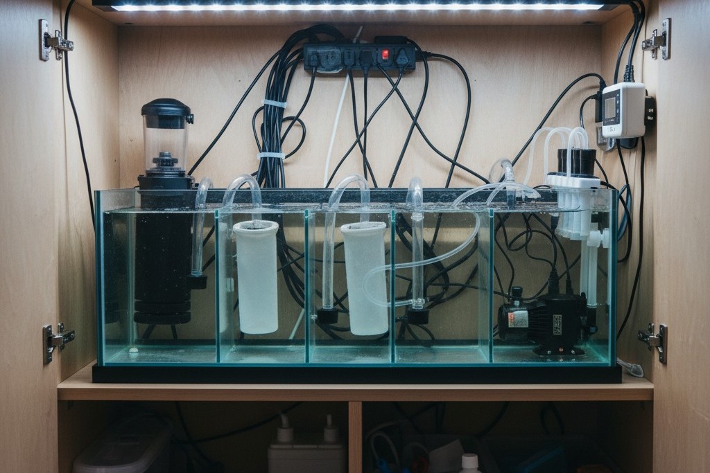
Placement dictates utility. A common mistake is mounting the strip directly in the center of the cabinet ceiling. This often casts the shadow of the operator’s head or hands directly onto the work area—the sump. If the user leans in to adjust a skimmer cup, they block their own light.
The correct position is on the front inside lip of the cabinet frame, angled inward at 45 degrees toward the back of the stand. This “stadium lighting” approach ensures the light source is always between the operator and the equipment, pushing shadows to the back of the cabinet where they do not matter. It illuminates the face of the equipment: the water level markings on the sump, the digital display of the heater controller, and the collection cup of the skimmer.
The goal is redundancy and risk reduction. This system exists to facilitate the maintenance of other systems. It should be ugly, robust, and invisible to the livestock. When the main pumps fail and the silence of the tank wakes the house, the ability to open a cabinet and instantly see the problem in 660nm clarity—without startling the fish or fumbling with a phone—is the difference between a minor maintenance event and a total tank crash.