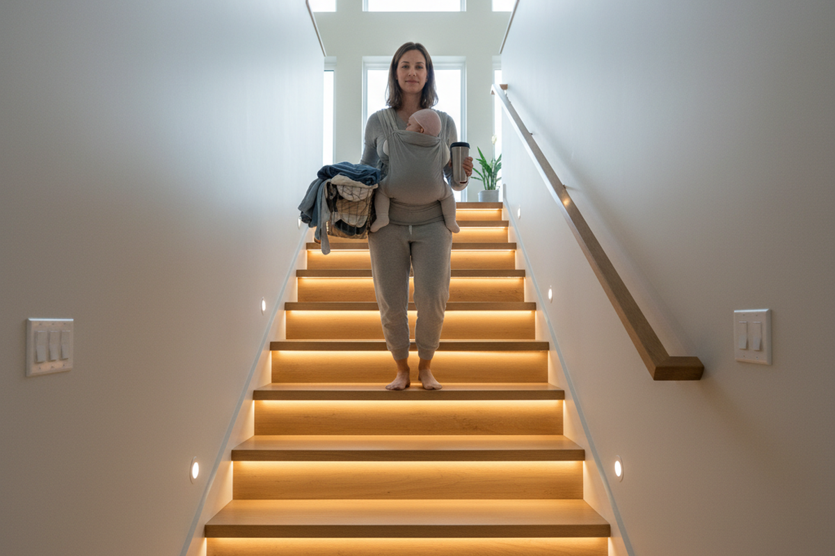
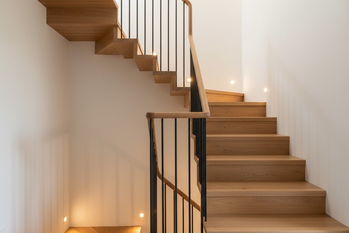
La escalera es un espacio de movimiento constante, pero automatizar su iluminación a menudo crea una pesadilla eléctrica. En lugar de una luz fluida y fiable, se obtiene el “estroboscopio de escalera”: un desastre parpadeante e impredecible donde las luces parpadean cuando alguien sube las escaleras o se niegan a responder a uno de los interruptores.
No se trata de un sensor de movimiento defectuoso. Es un esquema de cableado defectuoso. Un circuito estándar de 3 vías se diseñó para interruptores mecánicos sencillos, e integrar un sensor inteligente en ese diseño antiguo sin una estrategia es buscar problemas. Un sistema limpio y fiable requiere un nuevo enfoque que establezca una jerarquía de control clara.
El conflicto de los cables viajeros: Por qué los viejos circuitos de 3 vías combaten la automatización
Un circuito convencional de 3 vías es un diseño ingenioso para controlar una luz desde dos puntos. Utiliza dos cables “viajeros” que discurren entre los interruptores. Piense en los interruptores como cambiadores de vía para la electricidad. Accionar cualquiera de los interruptores interrumpe una ruta eléctrica y completa otra, encendiendo o apagando la luz.
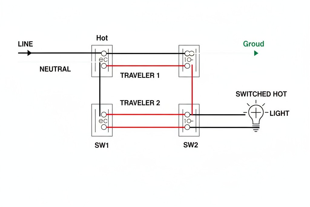
El diseño es sencillo, pero tiene un fallo fatal para la automatización: en un momento dado, solo uno de los dos cables viajeros tiene corriente. Un sensor de movimiento, al ser un dispositivo electrónico, necesita un suministro constante de energía para su cerebro interno. No puede funcionar si su propia fuente de alimentación es interrumpida por un segundo interruptor al final del pasillo. Cuando se instala un sensor en una configuración tradicional de 3 vías, el sensor y el interruptor mecánico terminan compitiendo por el control, creando el comportamiento errático que afecta a tantos proyectos.
Inspírese con los portafolios de sensores de movimiento Rayzeek.
¿No encuentra lo que busca? No se preocupe. Siempre existen formas alternativas de resolver sus problemas. Quizá alguno de nuestros portafolios pueda ayudarle.
El punto de mando: Por qué el sensor va en la caja de línea
Para construir un circuito inteligente estable, un dispositivo debe tener la última palabra. El sensor de movimiento debe ser el controlador principal, decidiendo cuándo recibe energía el circuito. El segundo interruptor se convierte simplemente en una forma de enviar una “solicitud” al sensor. Para que esto funcione, el sensor debe instalarse donde la alimentación entra al circuito.
En cualquier configuración de 3 vías, una caja eléctrica contiene el cable de “línea” del cuadro de distribución y la otra contiene el cable de “carga” que va a la luminaria. Al colocar el sensor Rayzeek en la caja del lado de la línea, lo posiciona para gestionar toda la energía entrante. Puede alimentarse de forma fiable y luego decidir si envía electricidad a la luz, según el movimiento o una señal del otro interruptor. Esta arquitectura transforma una lucha de poder en un sistema ordenado con una cadena de mando clara.
Localización de la fuente de alimentación: El primer paso
Antes de tocar un solo cable, debe encontrar la caja del lado de la línea. En primer lugar, corte la corriente del circuito en el cuadro de distribución.
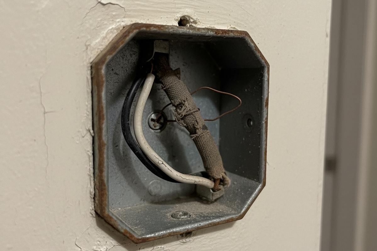
Con el circuito sin energía, retire ambas placas de pared y extraiga los interruptores de sus cajas, dejando los cables conectados por el momento. Asegúrese de que no haya cables pelados en contacto entre sí ni con ninguna superficie metálica. Ahora, vuelva a activar el interruptor automático. Con un comprobador de tensión sin contacto, revise cuidadosamente los cables de cada interruptor. En una caja, un solo cable (normalmente negro) tendrá corriente. Esa es su caja del lado de la línea, donde irá el sensor Rayzeek. La otra caja, donde ningún cable tiene corriente, es la caja del lado de la carga. Una vez localizada, vuelva a desconectar la alimentación en el interruptor automático antes de hacer cualquier otra cosa.
El patrón de cableado definitivo
Con la alimentación desconectada y la caja del lado de la línea identificada, puede rearmar el cableado del circuito. Este patrón reutiliza uno de los cables viajeros como un enlace de comunicación dedicado.
¿Busca soluciones de ahorro de energía activadas por movimiento?
Póngase en contacto con nosotros para obtener sensores de movimiento PIR completos, productos de ahorro de energía activados por movimiento, interruptores con sensor de movimiento y soluciones comerciales de presencia/vacancia.
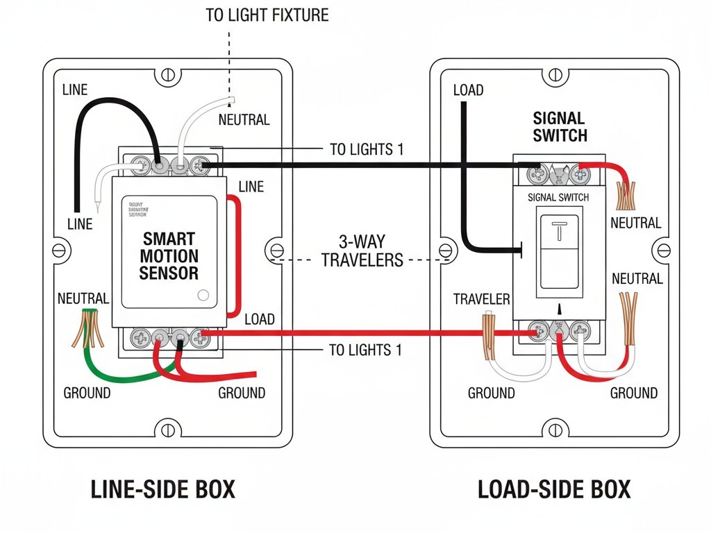
En la caja del lado de la línea (sensor): El sensor Rayzeek va aquí.
- Conecte el cable de “línea” negro (el que identificó con corriente) al sensor Línea borne.
- Agrupe los cables neutros blancos de la caja con el del sensor Neutro cable.
- Conecte los cables de tierra al tornillo de tierra del sensor. Esto proporciona la alimentación constante que el sensor necesita.
- Elija un cable conmutador (a menudo rojo) para que sea su cable de señal. Conéctelo al del sensor Conmutador borne (o de señal).
- Conecte el segundo cable conmutador al del sensor Carga borne. Este cable llevará ahora la alimentación conmutada a la luz.
En la caja del lado de la carga (interruptor): Aquí va un interruptor conmutador estándar de 3 vías, pero su función es más sencilla.
- Localice el cable conmutador que proviene del sensor Carga borne. Conéctelo directamente al cable que va a la luminaria, omitiendo el interruptor por completo.
- Localice el otro cable conmutador (su cable de señal). Conéctelo al común tornillo (de color oscuro) del interruptor conmutador.
- Conecte el borne del cable conmutador restante del interruptor de nuevo a una fuente con tensión para completar el circuito de señalización, siguiendo el diagrama específico de su sensor. Este interruptor ya no controla la luz directamente; solo envía una señal al sensor.
Detenga el parpadeo: establezca un tiempo de espera más largo
Una vez finalizado el cableado, el ajuste final se realiza en la configuración del sensor. El parpadeo constante en las escaleras suele deberse casi siempre a un retardo del tiempo de espera demasiado corto. Si el retardo se establece en un minuto, las luces pueden apagarse mientras alguien aún está en la escalera y reactivarse al instante, lo que provoca ese molesto destello.
Quizás le interese

- Tensión: 2 pilas AAA
- Modo Día/Noche
- Temporización: 15 min, 30 min, 1 h (por defecto), 2 h
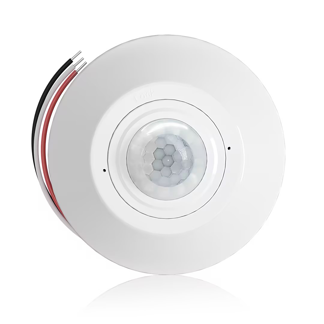
- Sensor de presencia PIR para montaje en techo con salida de relé de contacto seco
- Alimentación de baja tensión de 12/24VDC o 12/24VAC
- Contactos de relé aislados COM, NO y NC para entradas de EMS, HVAC y control de edificios
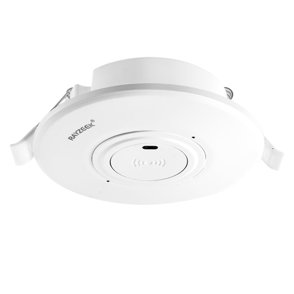
- Interruptor con sensor de movimiento por microondas empotrable en techo de baja tensión DC
- Entrada de 12 VDC / 24 VDC con rango de 10-30 VDC
- Corriente de funcionamiento máxima de 10A con retardo de tiempo, umbral de Lux y sensibilidad ajustables
- Interruptor con sensor de movimiento por microondas empotrable en techo para cargas más elevadas
- Entrada de tensión de red de 100-265 VAC, modelo de 10A
- Detección por microondas de 5,8 GHz con temporizador, umbral Lux y sensibilidad ajustables
- Interruptor con sensor de movimiento por microondas empotrable para techo
- Entrada de tensión de red de 100-265 VAC, modelo de 5A
- Detección por microondas de 5,8 GHz con temporizador, umbral Lux y sensibilidad ajustables
- Regulador con sensor de presencia PIR RZ037 de techo para alimentación de 220V
- Corriente de funcionamiento máxima de 3A con carga nominal de 660W
- El botón LUX controla el encendido/apagado del sensor de luz y la regulación de brillo ajustada por el usuario
- Regulador con sensor de presencia PIR RZ037 de techo para alimentación de 110V
- Corriente de funcionamiento máxima de 3A con carga nominal de 330W
- El botón LUX controla el encendido/apagado del sensor de luz y la regulación de brillo ajustada por el usuario
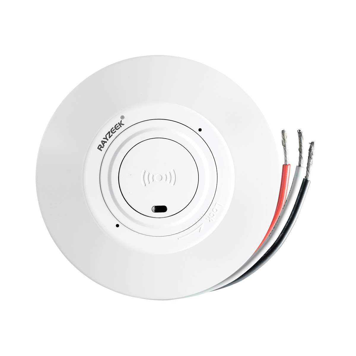
- Interruptor con sensor de movimiento por microondas de techo para CC de bajo voltaje
- Entrada de 12 VDC / 24 VDC con rango de 10-30 VDC
- Corriente de funcionamiento máxima de 10A con retardo de tiempo, umbral de Lux y sensibilidad ajustables
- Interruptor con sensor de movimiento por microondas de techo para mayor carga
- Entrada de tensión de red de 100-265 VAC, modelo de 10A
- Detección por microondas de 5,8 GHz con temporizador, umbral Lux y sensibilidad ajustables
- Interruptor con sensor de movimiento por microondas de techo
- Entrada de tensión de red de 100-265 VAC, modelo de 5A
- Detección por microondas de 5,8 GHz con temporizador, umbral Lux y sensibilidad ajustables
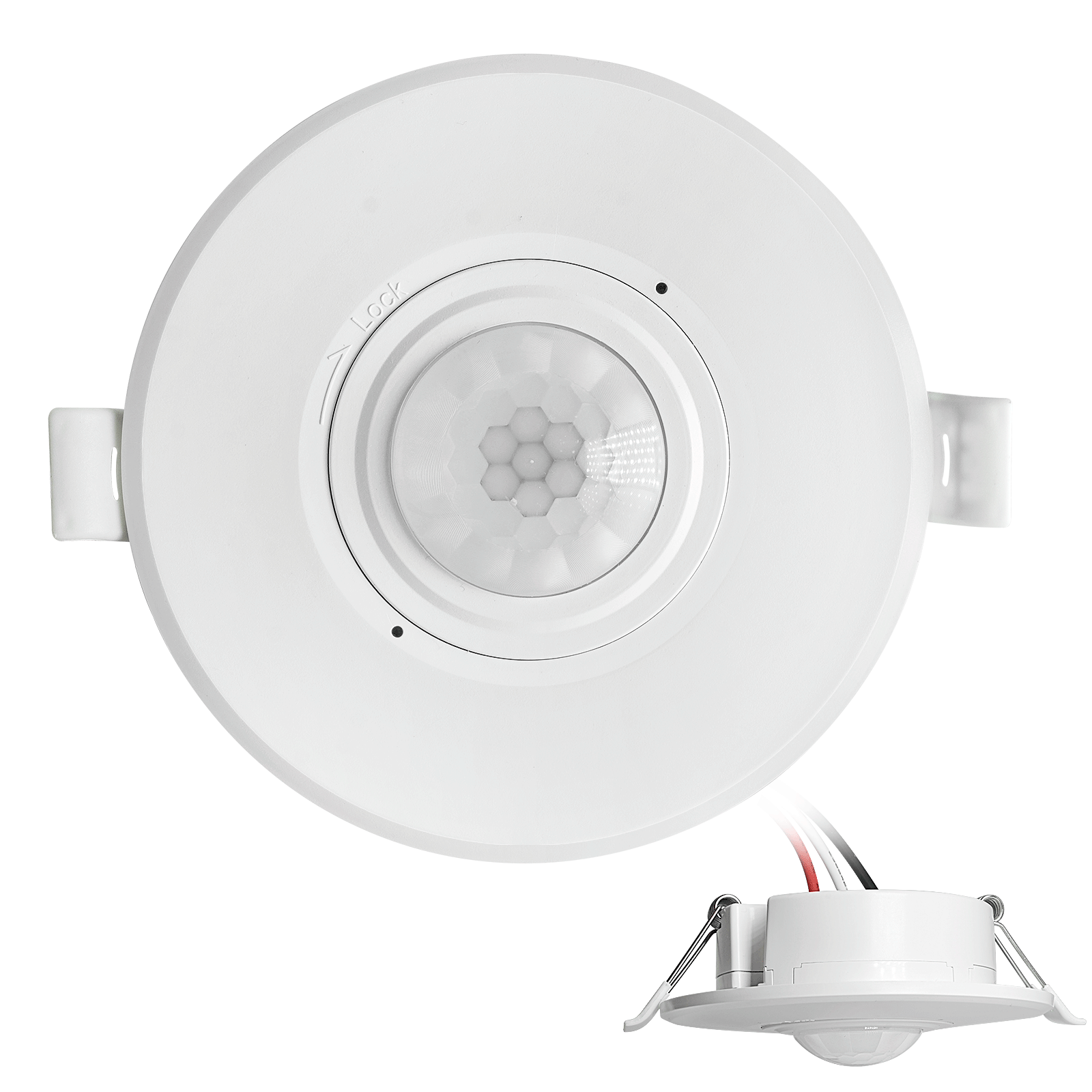
- Interruptor con sensor de movimiento PIR para montaje empotrable en techo de CC de bajo voltaje
- Entrada de 12 VDC / 24 VDC con rango de 10-30 VDC
- Corriente máxima de trabajo de 10 A con tiempo de retardo, umbral de luxes y sensibilidad ajustables
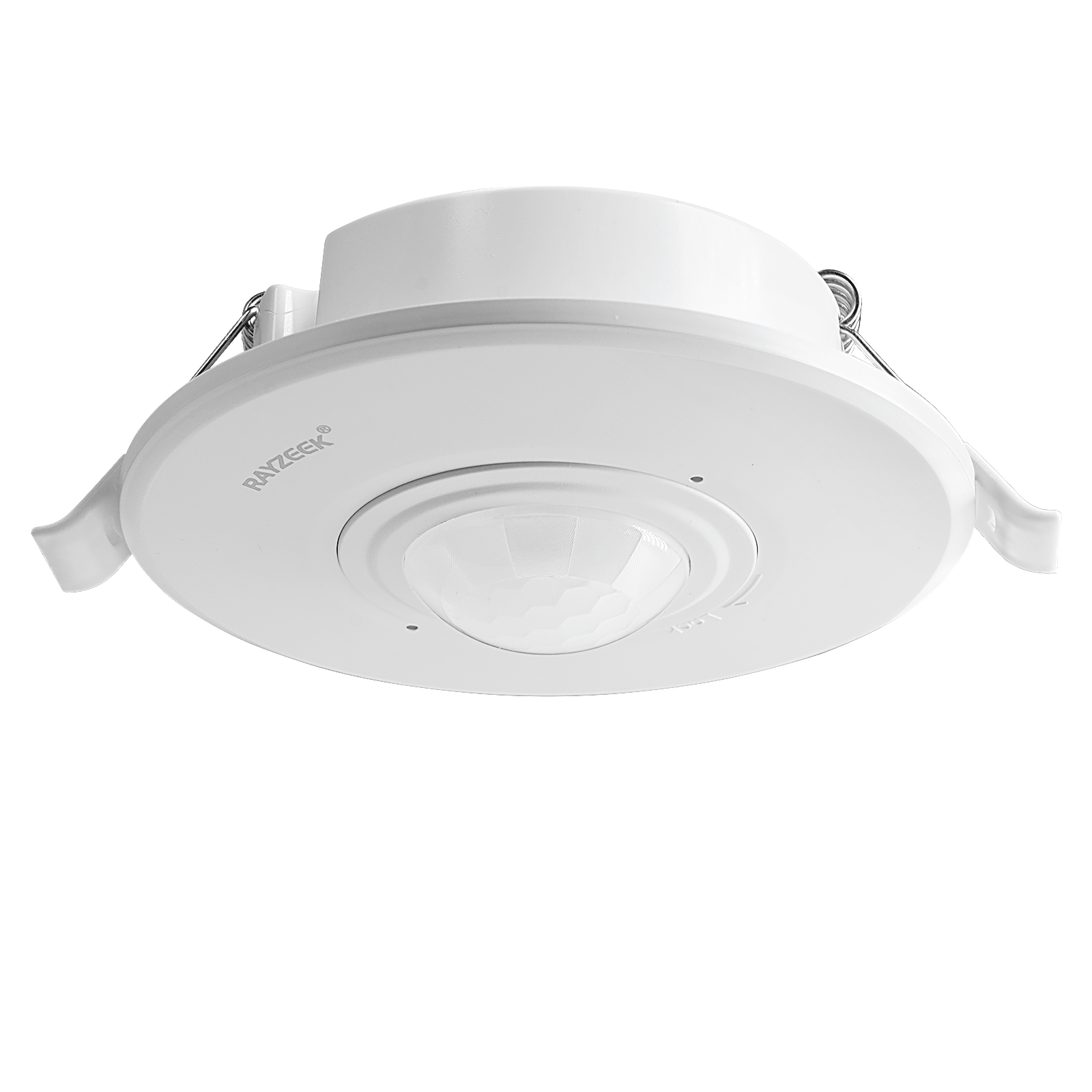
- Interruptor con sensor de movimiento PIR empotrable en techo para mayor carga
- Entrada de tensión de red de 100-265 VAC, modelo de 10A
- Detección de 360 grados con tiempo de retardo, umbral de luxes y sensibilidad ajustables
- Interruptor con sensor de movimiento PIR empotrable en techo
- Entrada de tensión de red de 100-265 VAC, modelo de 5A
- Detección de 360 grados con tiempo de retardo, umbral de luxes y sensibilidad ajustables
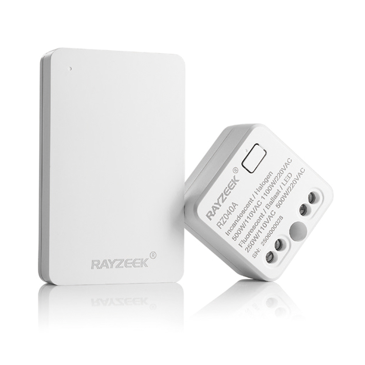
- Kit de emisor inalámbrico y receptor para el control de iluminación de encendido/apagado en interiores
- Receptor de 100-230 V CA, 50/60 Hz con corriente nominal de 5 A
- Interruptor inalámbrico alimentado por CR2032 con comunicación de 2,4 GHz
- Presencia (encendido automático/apagado automático)
- 12–24 V CC (10–30 V CC), hasta 10 A
- Cobertura de 360°, 8–12 m de diámetro
- Tiempo de retardo de 15 s a 30 min
- Sensor de luz Desactivado/15/25/35 Lux
- Sensibilidad alta/baja
- Modo de presencia con encendido/apagado automático
- 100–265V CA, 10A (requiere neutro)
- Cobertura de 360°; diámetro de detección de 8–12 m
- Temporización: 15 s–30 min; Lux OFF/15/25/35; Sensibilidad Alta/Baja
- Modo de presencia con encendido/apagado automático
- 100–265V CA, 5A (requiere neutro)
- Cobertura de 360°; diámetro de detección de 8–12 m
- Temporización: 15 s–30 min; Lux OFF/15/25/35; Sensibilidad Alta/Baja
Para escaleras y pasillos largos, es fundamental disponer de un tiempo de espera más largo. Ajuste el retardo de tiempo del sensor Rayzeek en un mínimo de tres a cinco minutos. Esto garantiza que la luz permanezca encendida durante todo el trayecto entre plantas, transformando un área con problemas de parpadeo en un recorrido iluminado de forma constante y fiable.
Diseñado para funcionar
Solucionar un circuito de 3 vías no consiste en encontrar un truco ingenioso. Se trata de aplicar un esquema de cableado que respete el funcionamiento real de la electricidad. Al otorgar al sensor el control primario en la caja del lado de la línea, se crea el sistema robusto y estable que caracteriza a la automatización profesional. Este esquema está diseñado para cumplir una función a la perfección: controlar la luz con absoluta fiabilidad, eliminando el parpadeo en las escaleras de forma definitiva.