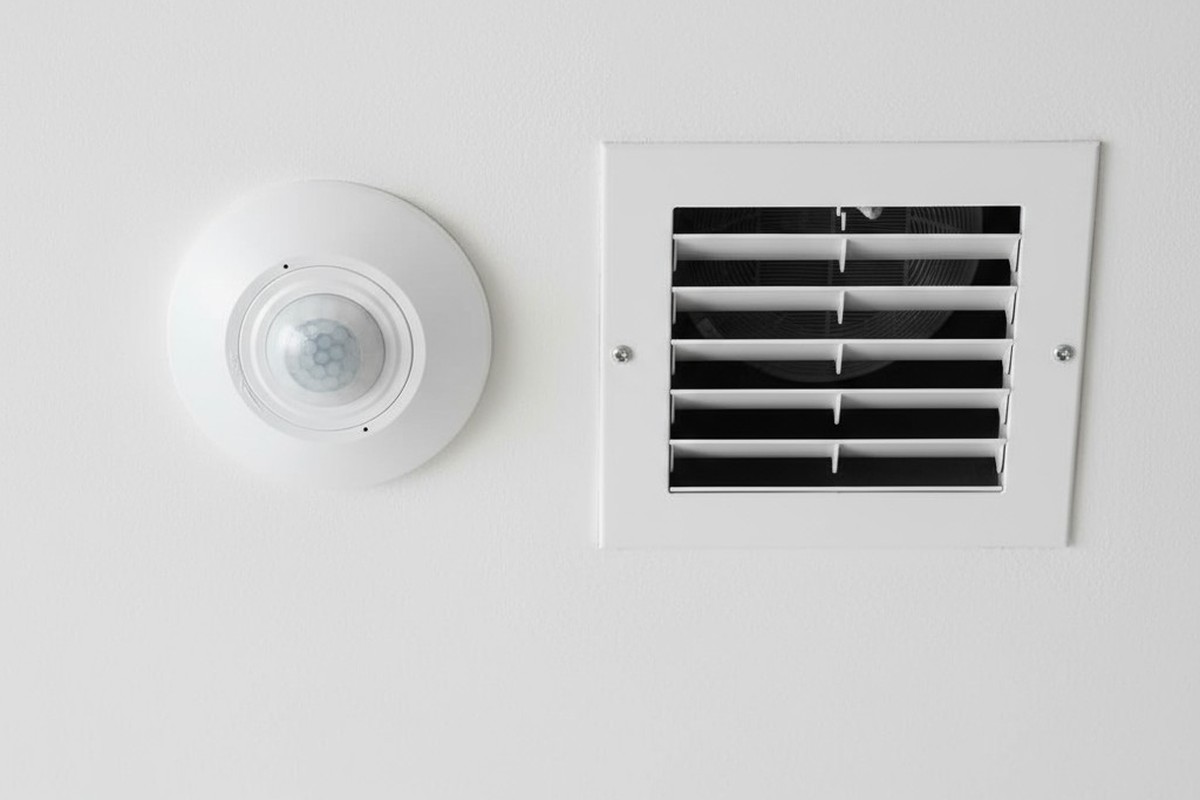
A light flickers on in an empty hallway. A security floodlight blasts an unoccupied yard. These are the small frustrations that undermine the promise of an automated space. When a motion sensor—a device built to respond to human presence—starts seeing ghosts, it morphs from a tool of convenience into a source of annoyance and wasted energy. The immediate reaction is to blame the device, to assume it’s faulty or just too sensitive.
But the truth is more subtle, rooted in the physics of the environment itself. The sensor isn’t broken; it’s being deceived. It is reacting perfectly to invisible events: currents of warm air, shifting patches of sunlight, and sudden drafts. This phenomenon, a form of thermal turbulence, creates phantom motion that can be understood and, more importantly, tamed through intelligent strategy, not just fiddling with a dial.
How a Sensor ‘Sees’ Heat: The Science of Passive Infrared
The most common type of motion sensor, Passive Infrared (PIR), doesn’t see motion like a camera. It sees heat. Specifically, it’s tuned to detect the wavelength of infrared radiation emitted by the human body. The term “passive” means the sensor emits no energy of its own; it simply watches for changes in the thermal landscape it monitors.
The Segmented Lens: A Grid of Detection Zones
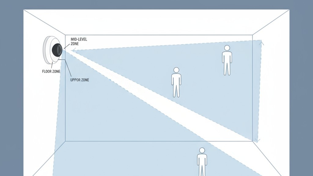
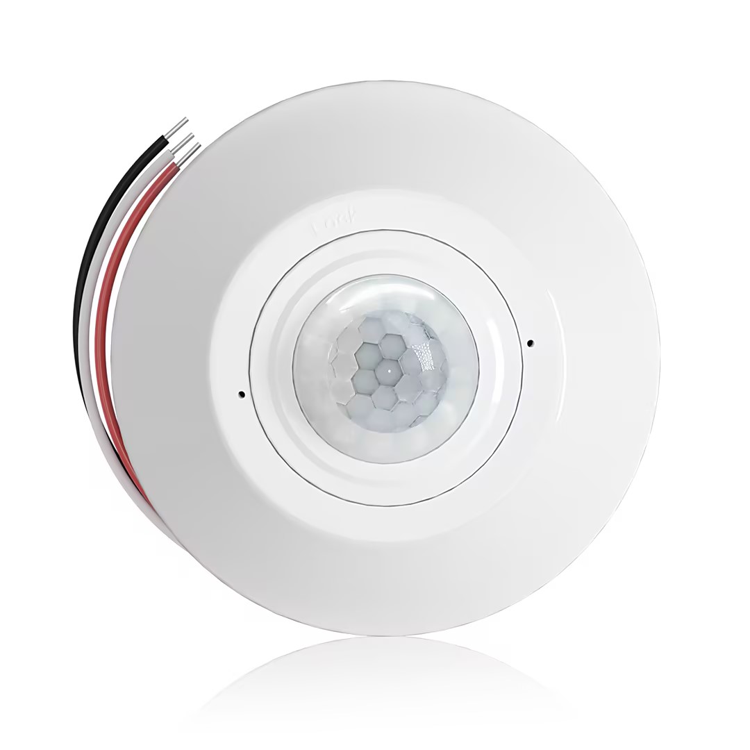
That domed, multifaceted plastic cover on a PIR sensor isn’t just for protection. It’s a critical component called a Fresnel lens. This lens takes a wide field of view and focuses it onto the tiny sensor element inside, but it does so in a fragmented way, effectively dividing the room into a grid of wedge-shaped detection zones. The sensor isn’t watching the room as a single picture, but as a series of distinct thermal segments.
From Stable to Spike: What Triggers a Sensor
In a still, thermally stable room, the sensor establishes a baseline reading for the infrared energy in each zone and is designed to ignore this static state. A trigger only occurs when an object with a different heat signature, such as a person, moves from one zone to another. This causes a rapid change—a sudden spike or dip in infrared energy detected first in one segment, then in an adjacent one. The sensor’s logic interprets this quick, sequential change across its zones as motion.
The Real Culprit: Thermal Ghosts in the Machine
The system works reliably until the environment introduces moving thermal events not attached to a person. These are the “thermal ghosts” that cause false triggers. A patch of sunlight on a cool floor, for instance, creates a pocket of warmth. As the sun moves, that warm patch creeps across the floor. If its path crosses from one of the sensor’s detection zones to another, the sensor sees a moving front of thermal energy and triggers an alert.
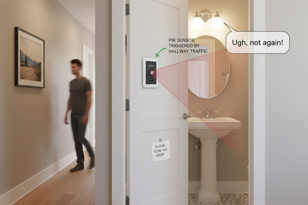
Air currents operate on the same principle. A gust of cold air from an open door, a draft from a leaky window, or a blast of hot air from an HVAC vent all represent a mass of air at a different temperature moving through the space. When this moving air crosses the sensor’s grid, it mimics the thermal signature of a person walking past, resulting in a false positive. The sensor is doing its job correctly; the environment is feeding it bad data.
¿Busca soluciones de ahorro de energía activadas por movimiento?
Póngase en contacto con nosotros para obtener sensores de movimiento PIR completos, productos de ahorro de energía activados por movimiento, interruptores con sensor de movimiento y soluciones comerciales de presencia/vacancia.
The ‘Maximum Sensitivity’ Fallacy
Faced with false triggers, many people reduce a sensor’s sensitivity. Conversely, if a sensor fails to detect motion, the instinct is to crank it to the maximum. But in the context of thermal turbulence, this is a flawed approach. Turning the sensitivity to its highest level doesn’t make the sensor smarter; it just lowers the threshold for what it considers a significant thermal event.
It amplifies the problem, not the solution.
A sensor on maximum sensitivity becomes exceptionally good at detecting the very things it should ignore: subtle air currents and minor temperature fluctuations. This often leads to more false triggers, deepening the user’s frustration and cementing the belief that the device is broken. True reliability comes not from a more reactive sensor, but from a cleaner environment and smarter logic.
The Placement Principle: Design for a Stable Environment
The most effective strategy for eliminating thermal false triggers is correct placement. Before you even touch a drill, the goal is to position the sensor where its view is as thermally stable as possible, aimed away from predictable sources of temperature change.
Map the Thermal Landscape
A brief observation of the space reveals its thermal patterns. Note where sunlight falls throughout the day, especially in the morning and evening. Identify the locations of HVAC vents, radiators, and large appliances. Consider how opening doors affects air circulation. This mental map is the key to finding the right mounting location.
Key Placement Rules
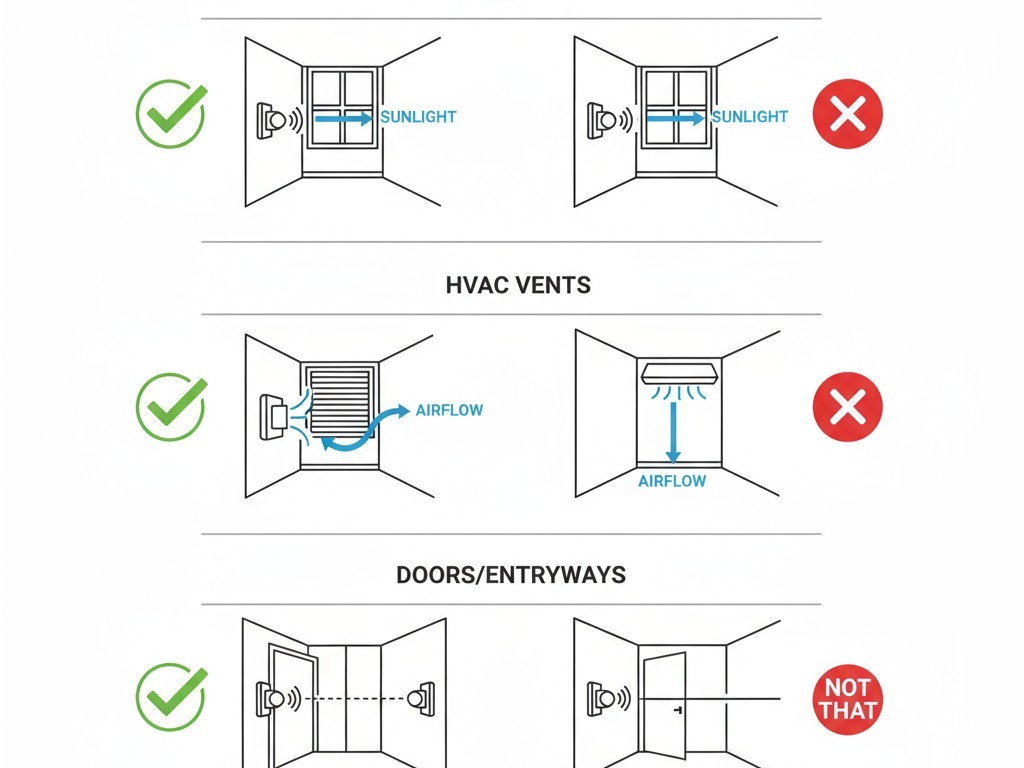
The primary rule is to aim the sensor’s field of view away from direct sunlight. If a sensor must be in a room with a large window, mounting it on the same wall as the window can be effective, as it won’t be looking directly at the thermal flux. Second, avoid aiming the sensor at or near an HVAC supply vent, a primary source of false triggers. Finally, in vestibules or entryways, position the sensor so its view is perpendicular to the door, not aimed at it. This prevents gusts of outside air from sweeping directly across its detection zones.
Quizás le interese

- Tensión: 2 pilas AAA
- Modo Día/Noche
- Temporización: 15 min, 30 min, 1 h (por defecto), 2 h
- Sensor de presencia PIR para montaje en techo con salida de relé de contacto seco
- Alimentación de baja tensión de 12/24VDC o 12/24VAC
- Contactos de relé aislados COM, NO y NC para entradas de EMS, HVAC y control de edificios
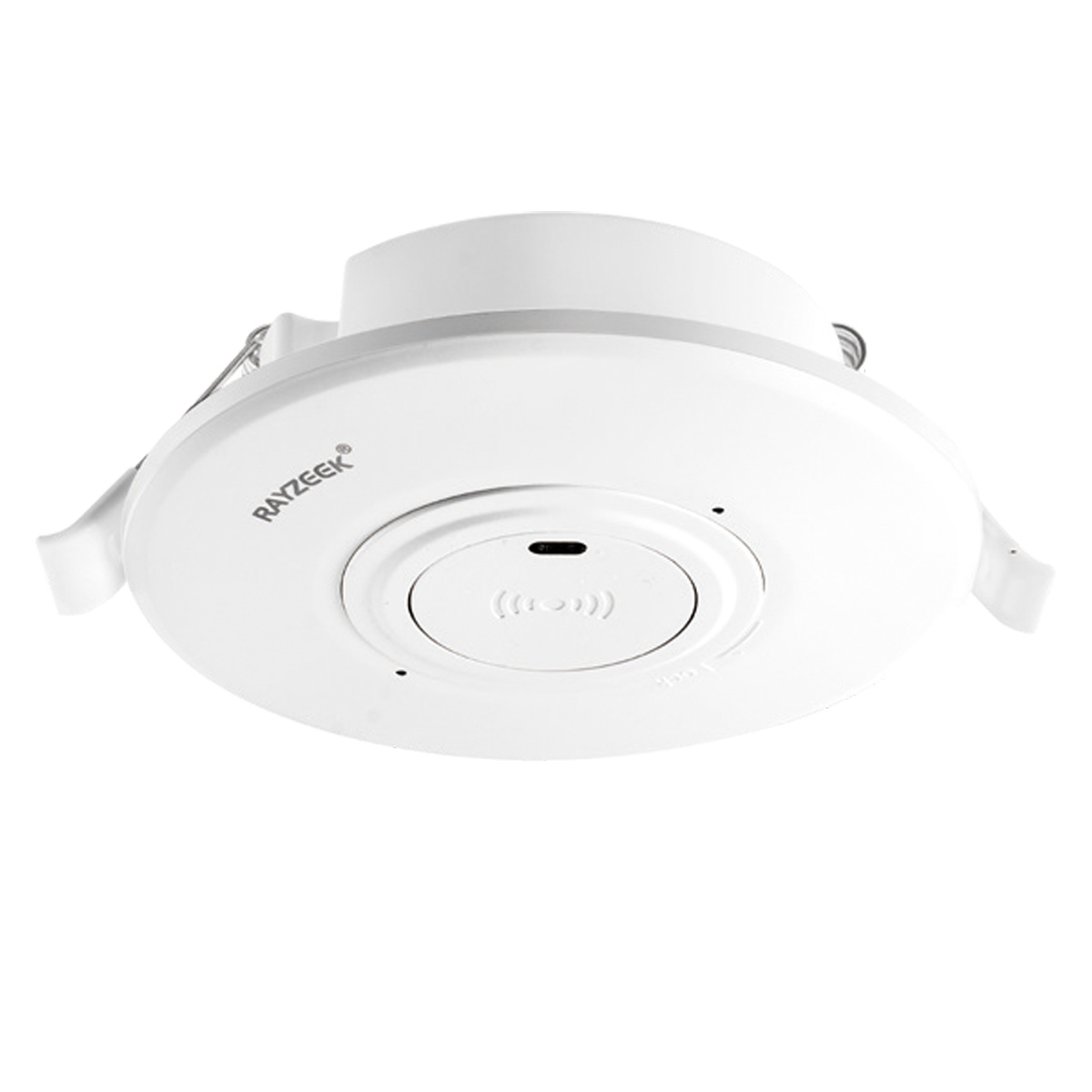
- Interruptor con sensor de movimiento por microondas empotrable en techo de baja tensión DC
- Entrada de 12 VDC / 24 VDC con rango de 10-30 VDC
- Corriente de funcionamiento máxima de 10A con retardo de tiempo, umbral de Lux y sensibilidad ajustables
- Interruptor con sensor de movimiento por microondas empotrable en techo para cargas más elevadas
- Entrada de tensión de red de 100-265 VAC, modelo de 10A
- Detección por microondas de 5,8 GHz con temporizador, umbral Lux y sensibilidad ajustables
- Interruptor con sensor de movimiento por microondas empotrable para techo
- Entrada de tensión de red de 100-265 VAC, modelo de 5A
- Detección por microondas de 5,8 GHz con temporizador, umbral Lux y sensibilidad ajustables
- Regulador con sensor de presencia PIR RZ037 de techo para alimentación de 220V
- Corriente de funcionamiento máxima de 3A con carga nominal de 660W
- El botón LUX controla el encendido/apagado del sensor de luz y la regulación de brillo ajustada por el usuario
- Regulador con sensor de presencia PIR RZ037 de techo para alimentación de 110V
- Corriente de funcionamiento máxima de 3A con carga nominal de 330W
- El botón LUX controla el encendido/apagado del sensor de luz y la regulación de brillo ajustada por el usuario
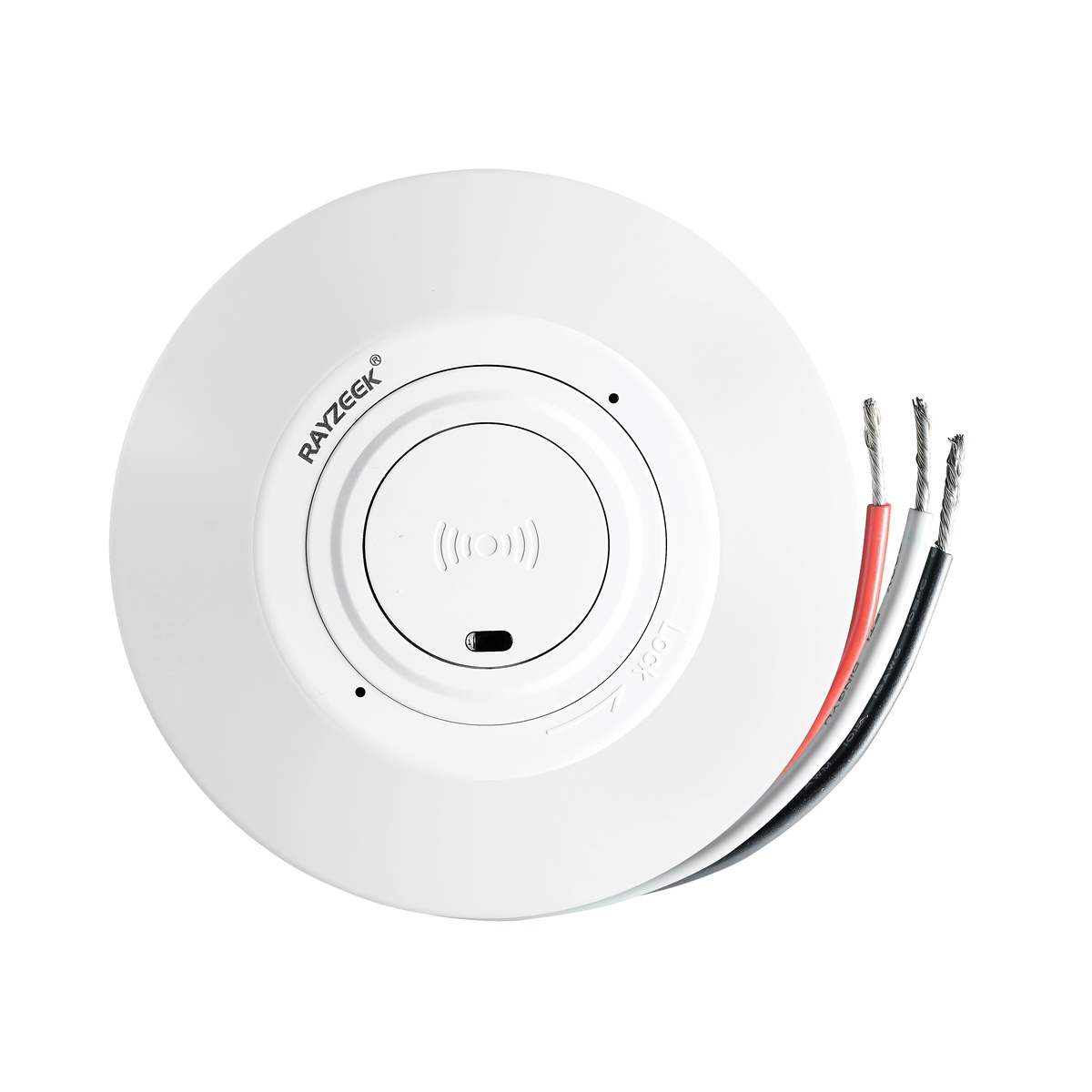
- Interruptor con sensor de movimiento por microondas de techo para CC de bajo voltaje
- Entrada de 12 VDC / 24 VDC con rango de 10-30 VDC
- Corriente de funcionamiento máxima de 10A con retardo de tiempo, umbral de Lux y sensibilidad ajustables
- Interruptor con sensor de movimiento por microondas de techo para mayor carga
- Entrada de tensión de red de 100-265 VAC, modelo de 10A
- Detección por microondas de 5,8 GHz con temporizador, umbral Lux y sensibilidad ajustables
- Interruptor con sensor de movimiento por microondas de techo
- Entrada de tensión de red de 100-265 VAC, modelo de 5A
- Detección por microondas de 5,8 GHz con temporizador, umbral Lux y sensibilidad ajustables
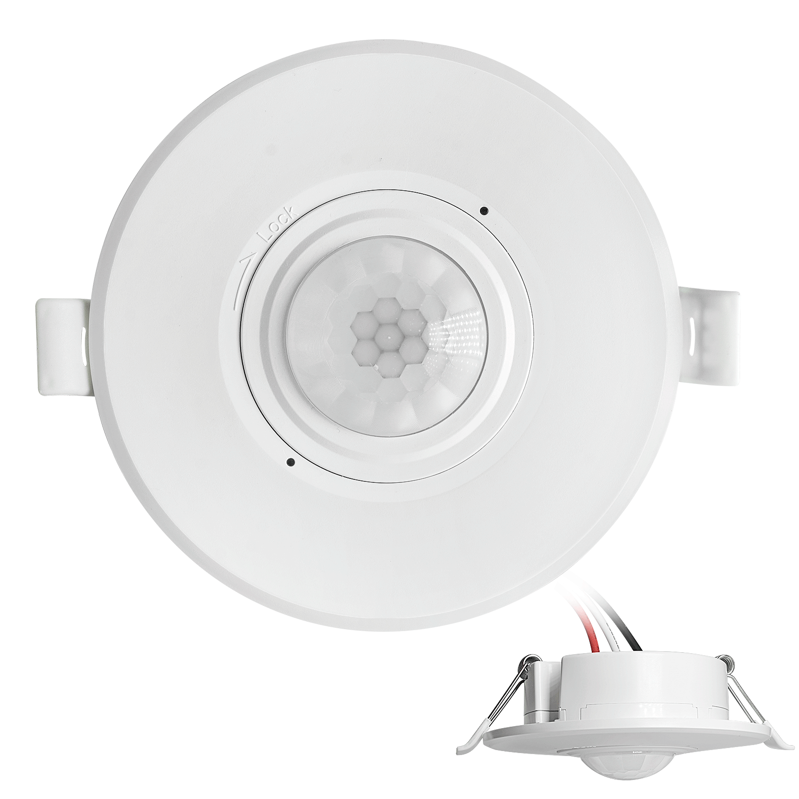
- Interruptor con sensor de movimiento PIR para montaje empotrable en techo de CC de bajo voltaje
- Entrada de 12 VDC / 24 VDC con rango de 10-30 VDC
- Corriente máxima de trabajo de 10 A con tiempo de retardo, umbral de luxes y sensibilidad ajustables
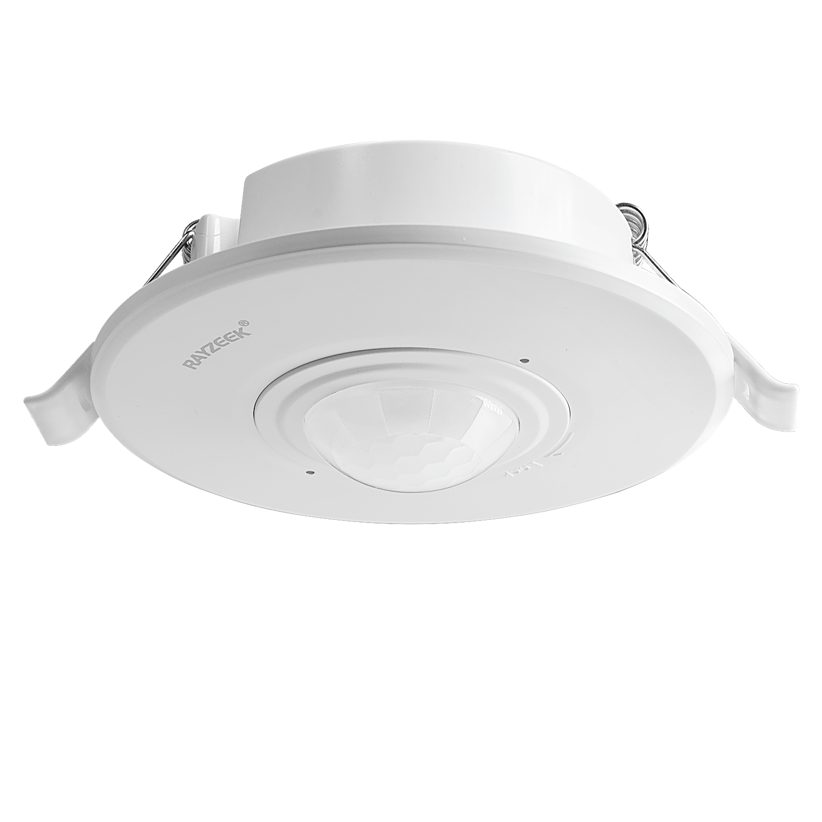
- Interruptor con sensor de movimiento PIR empotrable en techo para mayor carga
- Entrada de tensión de red de 100-265 VAC, modelo de 10A
- Detección de 360 grados con tiempo de retardo, umbral de luxes y sensibilidad ajustables
- Interruptor con sensor de movimiento PIR empotrable en techo
- Entrada de tensión de red de 100-265 VAC, modelo de 5A
- Detección de 360 grados con tiempo de retardo, umbral de luxes y sensibilidad ajustables
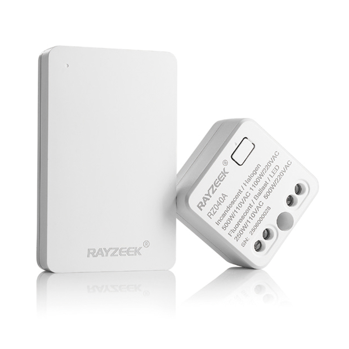
- Kit de emisor inalámbrico y receptor para el control de iluminación de encendido/apagado en interiores
- Receptor de 100-230 V CA, 50/60 Hz con corriente nominal de 5 A
- Interruptor inalámbrico alimentado por CR2032 con comunicación de 2,4 GHz
- Presencia (encendido automático/apagado automático)
- 12–24 V CC (10–30 V CC), hasta 10 A
- Cobertura de 360°, 8–12 m de diámetro
- Tiempo de retardo de 15 s a 30 min
- Sensor de luz Desactivado/15/25/35 Lux
- Sensibilidad alta/baja
- Modo de presencia con encendido/apagado automático
- 100–265V CA, 10A (requiere neutro)
- Cobertura de 360°; diámetro de detección de 8–12 m
- Temporización: 15 s–30 min; Lux OFF/15/25/35; Sensibilidad Alta/Baja
- Modo de presencia con encendido/apagado automático
- 100–265V CA, 5A (requiere neutro)
- Cobertura de 360°; diámetro de detección de 8–12 m
- Temporización: 15 s–30 min; Lux OFF/15/25/35; Sensibilidad Alta/Baja
Shielding the Sensor: Physical Fixes for Problem Spots
Sometimes, ideal placement isn’t an option. A room’s layout or wiring constraints might force a sensor into a location exposed to thermal interference. In these cases, physical modifications can shield the sensor from the source of the problem.
Inspírese con los portafolios de sensores de movimiento Rayzeek.
¿No encuentra lo que busca? No se preocupe. Siempre existen formas alternativas de resolver sus problemas. Quizá alguno de nuestros portafolios pueda ayudarle.
The Power of Shade
A simple but effective solution is to create a “visor” or “hood” for the sensor. This small shield, mounted just above the lens, can block high-angle sunlight from creating moving hot spots in the sensor’s view. Similarly, recessing the sensor slightly into a ceiling or wall uses the surrounding structure as a natural shield.
Strategic Masking
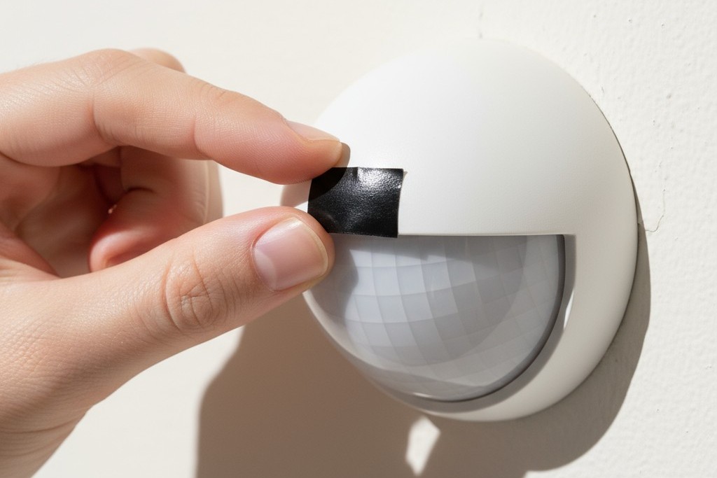
For a more targeted approach, you can “blind” the sensor to a specific problem area. By placing a small piece of opaque electrical tape over a specific facet of the Fresnel lens, you block its ability to see the corresponding zone. If a single HVAC vent is causing all the trouble, identifying and masking the part of the lens that covers it can be a surgical fix that leaves the rest of the detection area fully active.
Intelligent Mitigation: Outsmarting the Environment with Logic
The most advanced solutions move beyond physical placement and into the realm of software. Modern systems can use additional inputs to make smarter decisions about whether a thermal event is worth acting on.
Lux Gating: Tying Motion to Ambient Light
Lux gating is a powerful feature that uses a sensor’s built-in light meter (photocell) to prevent false triggers from sunlight. The logic is simple: if the sensor’s main job is to control lights, there’s no need to turn them on when the sun is already flooding the room. The system can be configured with a “lux gating” threshold. When the ambient light level is above this point, motion sensing is disabled. This elegantly solves the moving sunbeam problem by telling the sensor to ignore motion during the brightest parts of the day.
While thermal turbulence is a primary cause of false triggers, other factors like small pets, insects on the lens, or electrical interference can also be culprits. But understanding and mitigating these invisible currents of heat and air is the most critical step toward creating a motion sensing system that is not just automated, but truly intelligent.